

Automatic Power Factor Controller using Microcontroller
Contents
The thirst for new sources of energy is unquenchable, but we seldom realize that we are wasting a part of the electrical energy every day due to the lagging power factor in the inductive loads we use. Hence there is an urgent need to avoid this wastage of energy.
Before getting into the details of Power factor correction, lets just brush our knowledge about the term “power factor”. In simple words power factor basically states how far the energy provided has been utilized. The maximum value of power factor is unity. So closer the value of P.F to unity, better is the utility of energy or lesser is the wastage. In electrical terms Power factor is basically defined as the ratio of the active power to reactive power or it is the phase difference between voltage and current. Active power performs useful work while Reactive power does no useful work but is used for developing the magnetic field required by the device.
Most of the devices we use have power factor less than unity. Hence there is a requirement to bring this power factor close to unity. Here we are presenting a prototype for automatic power factor correction using PIC Microcontroller.
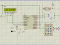
Circuit Diagram

Working
Comparator Section
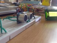
The 230 V, 50 Hz is step downed using voltage transformer and current transformer is used to extract the waveforms of current. The output of the voltage transformer is proportional to the voltage across the load and output of current transformer is proportional to the current through the load. These waveforms are fed to Voltage Comparators constructed using LM358 op-amp. Since it is a zero crossing detector, its output changes during zero crossing of the current and voltage waveforms. These outputs are fed to the PIC which does the further power factor calculations.
Microcontroller Section
Correction Section
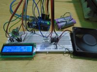
Power Factor Correcting capacitor connected parallel to load through relay, if the relay is energized by microcontroller it will connect the capacitor parallel with load, if relay deenergized it will remove the capacitor from the load. When the resistive load is on the power factor will be near to unity so the microcontroller doesn’t energize the relay coil. When the inductive load is on the power factor decrease now the microcontroller energize the relay coil in order to compensate the excessive reactive power. Hence according to the load the power factor is corrected.
MikroC Program
//LCD Module Connections
sbit LCD_RS at RB2_bit;
sbit LCD_EN at RB3_bit;
sbit LCD_D4 at RB4_bit;
sbit LCD_D5 at RB5_bit;
sbit LCD_D6 at RB6_bit;
sbit LCD_D7 at RB7_bit;
sbit LCD_RS_Direction at TRISB2_bit;
sbit LCD_EN_Direction at TRISB3_bit;
sbit LCD_D4_Direction at TRISB4_bit;
sbit LCD_D5_Direction at TRISB5_bit;
sbit LCD_D6_Direction at TRISB6_bit;
sbit LCD_D7_Direction at TRISB7_bit;
//End LCD Module Connections
int powerFactor()
{
  int a=0,b=0,t=0,x=0;
  float tm,pf;
  TMR1L=0;
  TMR1H=0;
  do
  {
    if(PORTA.F0 == 1)
    T1CON.F0 = 1;
    else if(PORTA.F0 == 0 && T1CON.F0 == 1)
    {
      T1CON.F0 = 0;
      break;
    }
  }while(1);
  a = (TMR1L | (TMR1H<<8)) * 2;
  TMR1L=0;
  TMR1H=0;
  do
  {
    if(PORTA.F0 == 1)
    {
      T1CON.F0=1;
      if(PORTA.F1==1)
      {
        T1CON.F0=0;
        break;
      }
    }
  }while(1);

  b = TMR1L | (TMR1H<<8);
  tm = (float)b/a;
  pf = cos(tm*2*3.14);
  x=abs(ceil(pf*100));

  return x;
}

void main()
{
  char c[]="0.00";
  int a,b,d,x,f,e;
  float tm,pf;

  Lcd_Init();
  Lcd_Cmd(_LCD_CURSOR_OFF); // Cursor off

  ADCON1 = 0x08; // To configure PORTA pins as digital
  TRISA.F0 = 1; // Makes First pin of PORTA as input
  TRISA.F1 = 1; //Makes Second pin of PORTA as input
  TRISD.F0 = 0; //Makes Fist pin of PORTD as output
  TRISD.F1 = 0; //Makes Second pin of PORTD as output

  while(1)
  {
    a = powerFactor();
    Delay_us(50);
    b = powerFactor();
    Delay_us(50);
    d = powerFactor();
    Delay_us(50);
    e = powerFactor();
    Delay_us(50);
    f = powerFactor();

    x = (a+b+d+f+e)/5;
    c[3]=x%10 + 0x30;
    x=x/10;
    c[2]=x%10 + 0x30;
    x=x/10;
    c[0]=x%10 + 0x30;

    Lcd_Out(1,1,"Power Factor");
    Lcd_Out(2,1,c);

    if(x<90)
    {
      PORTD.F0 = 1;
      PORTD.F0 = 1;
      Delay_ms(2000);
    }
    else
    {
      PORTD.F0 = 0;
      PORTD.F0 = 0;
    }
    Delay_ms(250);
  }
}
The function powerFactor() will find the current power factor by using the Timer 1 module of PIC 16F877a. Power Factor may be fluctuating, so to avoid it we will find power factor more than one time and its average is taken.
Note : This is only a prototype of Automatic Power Factor Controller, for practical implementation you may need to make some modifications in the program and circuit.


I want details everything with full code of automatic power factor correction using microcontroller..can I get?
Hi Swapnil,
What help you need ?
Can you help for this project?
Can the owner of this code contact me so that he can explain how to make this code run
Hello sir can you please send me the corrected code .
My E-mail is – [email protected]
Hi ..It compiled with out any error for me. But i don’t know how to put a load in proteus to make low pf in supply
pls help
I am planning to simulate this in proteus as i don’t require to do this in real hardware. Is the pf correction section now correct? and how to insert a load to make pf low in proteus?
We are getting error for abs and cos tetms in mikroC complier…wt to do??
Is this the correct code?
Sir, how can we write th abovecode using AVR
Hello. Is the program for the correction part correct?
hello sir, have you a coding of this practical in 8051 family controller like AT89s51?
Hi, Divya shamka I am working in NFL , I want ask you that the above programm for automatic power controller by pic , can be written in assembly language , if yes please write it in assembly.
Thanks with regards.
You can build the above program with MikroC Pro compiler.
hey man i will be thankfull wholeheartedly if u can send me the .hex file of this programm to my mail [email protected].i urgently need it man
how to caliberate?
Sir how can i get Current transformer in proteus?
thank you.
how u get current pulse?
Dear
How to adopt your code for STM32F103 ?
Can you send me proteus simulation. Thanks
What is the rating of CT and PT, what inductance should i use on primary and secondary side transformer?
sir can i get the simulation file for this project
kindly send it to [email protected]
This is only a prototype of Automatic Power Factor Controller, for practical implementation you may need to make some modifications in the program and circuit.
Ligo please help me, when i running this code in simulation it give
an error of “stack underflow” please correct this error or send me the
correct code its not working and how to improve power factor correction using pic 8051
how to improve power factor correction using pic 8051
Ligo please help me, when i running this code in simulation it give
an error of “stack underflow” please correct this error or send me the
correct code its not working.
I am Vignesh I have error in float tm,pf;
vignesh
sir, i try but not propery work, please send corrected code
please send me your hitech compiler code, i want this code because i use hitech compiler and mplab IDE… [email protected]
in the last of the code write demo limit ? what is mean how can i remove this error
i don’ t know why this program did not compile. can i know what exact version of mikroC it has written for. thank you?
Sir can I ask complete code? please send to email: [email protected]
I didn’t do any simulation for this project. Only tested in real hardware.
It will work fine in MikroC Pro.
Thanks for the feedback.
email me at [email protected]
Lots of error when I complied program I’m micro c pro
Hey man thanks for the code, got it kicking on Proteus 8. Have had an exciting past day since i couldn’t use microc (2k limit). So I translated your code into Hitech C. And just a pointer,,,,, ADCON1 = 0x06 if you want to make all of PORTA pins digital input. Again, thanks for sharing, really helpful you guys.
You can generate it using MikroC Pro compiler.
Sorry, we don’t have the hex file. You can compile and generate it.
We are not providing the hex file as the project is not complete. Its power factor measuring section is correct, but correction is not correct.
You can use the compiler MikroC Pro for doing it.
pleas send me the materials and theire properties that you use on proteus software on “[email protected]” i make mistak when i constract the circuit.
Sir plzz can u share me the .hex file… Email.I’d:- [email protected]
iam not able to generate hex file because my compiler is a demo version …so plz send me the hex file or suggest wat to do to generate hex file ….if u tel me to buy original version of micro c pro …its costlier..i can’t afford tat much moneyy so kindly give me some other option
mail id: [email protected]
Sir plzzz tell how to burn this code to controller…
And how to create .hex file
There is no download for this. You can take the program above.
You need to select proper power factor selection capacitors depending on your load requirements.
You need to improve power factor correction mechanism of the program.
sir! im getting difficlty in running the program! can u plz check and send me the exact code?
mail : [email protected] please! a kind request!
how to download this project
how i made corrections or improve that sections.
if u dont mine please give me an idea.
You can use a CT depending on the maximum current required for your load.
No you need to improve that section. It is not completely correct. But reading section is correct.
Hey can u tell the rating of ct for above circuit . I just need a reference as to by what value current should be reduced???
thanks sir and i have another doubt is this program corrects the pf automatically.
No need of rectifier. The comparator will compare and will produce pulses.
The secondary winding of the transformer is connected to LM358. transformer out is AC is this affect LM358.Or it required any rectifer.please tell me.
Iam doing this project now can you please send more information about this project and the program i really dont have much program skill so please help my mail id [email protected]
Upload the hex file of this code this would be easier to dump to PIC
Please send hex file
sir please tell me the reference values of the current and voltage transformers
hello please sir what is the reference values of the voltage and current transformers on the power factor correction circuit you can reply me on [email protected] thanks sir.
Sorry, currently we don’t have any files of this project.
@@lijoppans:disqus sir plz send me the proteus version of this project
plz send me the proteus file of this project
Sorry, I don’t have this project with any other microcontrollers.
Current transformers are commonly available now a days. You can even get it online.
current transformer is not avilable so as well as pulse wave genrator use it
1. Verify All Connections.
2. Adjust the Contrast of LCD
3. Make sure that PIC Program is running, check crystal, power supply etc.
The program is only showing black boxes on the LCD when done on hardware..what to do? I checked all my connections
It is not a Syntax Error…
It is MikroC Demo Limit error…
sir i am getting these errors…what to do
plz send me hex file
[email protected]
sir whenever i tried to built the programme its showing demo limit in micro c pro …so iam not able to generate hex file because my compiler is a demo version …so plz send me the hex file or suggest wat to do to generate hex file ….if u tel me to buy original version of micro c pro …its costlier..i can’t afford tat much moneyy so kindly give me some other option
mail id: [email protected]
can you help me with pic microcontroller based ic tester for 74 series
here is my email “[email protected]
“
Sorry we don’t have any other codes.
Please send me the corrected code
@[email protected]
Please send me a correct [email protected]……tq
Basic function is explained in the article itself. The configuration of Timer 1 is not explained.. it differs from microcontroller to microcontroller.
can you give more explanation on the program please
These are built in library functions of MikroC Pro compiler… they don’t require header files..
You should wind transformers depending on your current and voltage ratings… … Design with 3V secondary voltage.
It depends on your applications… You can use transformers with 3V secondary voltage..
will u please tell about the CT and PT ratings, i mean their turn ratio and current rating
what should the rating of CT and PT
You can build the above code to generate hex.
Plz send hex code
[email protected]
Output voltage always depends on the input … I said about maximum / rms.
that’s what I’m asking is that the op voltage of the both should be equal .
Sorry, I don’t have Hi-Tech or XC8 codes.
No, I said the output voltage rating of both transformers.
when i Compiled it . error as
error: 0 434 Demo Limit Demo Limit
error: 0 102 Finished (with errors): 23 Dec 2014, 01:25:07 Automatic Power Factor Controller.mcppi
its means generated hex file limit exceed to 2k .
so pl post it hi-tech or xc8 ver. code
ur mean to say both rating (potential transformer & current transformer) are equal (same) ?
Use default mikroc settings.
use a 3V transformer.
use a 3V output transformer.
pl tell me here whats its conflagration bit setting ?
what is rating of current transformer
what are ratings of potential ¤t transformers
You might not be able to simulate above project in proteus properly… Try in real hardware..
I have tried this programme but it isn’t working with proteus simulation. Can you send me hex file for this programme?
My email id is: [email protected].
the code compiled successfully, just be smart on how you go about it in Micro C pro.
Okay Mr.Ligo thanks for positive response. my hardware its almost ready i hope it will work.
Hello,
The above code is correct, it will work…. only problems is that power factor correction section needs improvement… There is no errors..
I think, it is not good to simulate projects like this…. Try in real hardware..
Ligo please help me, when i running this code in simulation it give an error of “stack underflow” please correct this error or send me the correct code its not working.
please i have to submit my project at the end of this month.
Design the capacitor ratings as per your power factor requirements..
sir . please send me the two capacitor ratings .
Yes, you can use it.
MikroC is a compiler while proteus is a simulator.. You can compile your code with MikroC to generate hex file.
did use multisim for this project???????
hi sir
i dont know how to create a hex file
i am doing the project in protecus???
is this good on going for that or whether i need to change the software ???
i dont how miroC works?????? can we build this same circut over there
We have no other codes.
hie can i have the correct code please. [email protected]
can you send me the correct of APFC.
at [email protected]
Hey Ligo please send me the corrected code too.
at my email adress
[email protected]
alright thank you so much, please guide me can i use normal step down 12v, 2A transformer in series for current measuring in lm358 ?
For voltage transformer you can use a 230/3V, 500mA transformer available in the market…
For current transformer.. you can wind depending on your requirements.. provide a secondary voltage about 3V.
what rating you use of current transformer and voltage transformer please reply. i m waiting for your concideration.
I have only above code.
Hi mr. ligo,appreciate if you able to send the full correct code to my email [email protected]…need to do for my house use.
If the clock frequencies are correct in mikroc project settings and pic properties in proteus..
Check the PIC used in mikroc project settings and proteus are same.. PIC 16F877A..
Note : 16F877 and 16F877A are different microcontrollers..
both clock frequency’s are same…btw i am not using CT & PT
I have only the above code.. It is written for MikroC Pro compiler..
It is working code.. only thing is it need improvement in the power factor correction section..
Above program is correct.. but it needs improvement in the power factor correcting section..
It is not a joke man. .It is 100% working… but it needs improvement.. in the power factor correction section..
Check clock frequencies in mikroc project setting and pic properties in proteus.
abs() – takes absolute value…
ceil() – rounds to nearest integer..
It depends on your requirements..
It is not good to simulate these projects in proteus..
Hey please tell me where i can find Current transformer in Proteus software ?
Hey please tell me where i can find current transformer in proteus ?
did you get the rating of current transformer and potential transfortmer ?
x=abs(ceil(pf*100)); can u explain about this??
bro,,,i worked with the pf calculation part only,,,& the code compiles fine,,,,,,,but when i tried it in proteus it gives error & Lcd is blank…
I said before this code is a joke, does not work.
could send me the corrected cod my sir?
[email protected]
Sir can I ask complete code? please send to email: [email protected]
really need for a project.
Thank you very much
Regards’
hi im doing the project with atmega 16 . i have made the required changes in this code to be compatible with atmega. the code compiles without error but nothing happens on proteus. kindly help me out with this. i have to submit my project very soon
what type of current transformer did you used?i mean the name of the transformer or no or something else that i can find and buy it
SEND CORRECTED CODE PLSS VERY URGENT
[email protected]
please sir send me correct code…..here…
[email protected]
and kindly also specified the version of microC pro…..Thankyou…
i don’ t know why this program did not compile. can i know what exact version of mikroC it has written for. thank you?
Please send me the corrected code because when i load his one on proteus nothing happens although it compiles without errors
my email [email protected]
can you please send me the corrected code on [email protected]
Did Some one practically implemented this? i tried but the display value changes randomly for the same load…
plz give me project detail
hey , please can you send me the file of this project i need it for my collage
my email: [email protected]
May be you could have longer delays.250ms is not enough at all. Since the power factor does not change quickly you could have delay at least 10seconds. Or give the user a configuration option to configure it.
There should be some header files. See your code does not include any header files , compiler crazy about where does that Lcd_init(); or Lcd_write() came from?
Please send me the corrected code because when i load his one on proteus nothing happens although it compiles without errors
my email is [email protected]
How to calculate the value of the capacitor bank
Hallo sir
Please send me the corrected code because when i load his one on proteus nothing happens although it compiles without errors
my email is [email protected]
can I run this code in mplab
hi can you please send me the corrected code?
my id is: [email protected]
Can you please mention in my email, what current sensor and what rating voltage transformer to use
Thank you
Hi , I am working on a similar project but for a 3 phase system. I would like to know how did you manage the problem of linearity and phase displacement of the CT in particula?
Sorry for the late replay..
Currently we aren’t providing any training.. I am ready to provide training personally… But I am not good in speaking English.
Wavelength of pulse..
a is the pulse width or wave length of pulse
I need pic programming training by Google talk or Skype
Online training means??
It is the measured timer value of current and voltage waves…
are you giving training on pic online?
tm = (float)b/a;
pf = cos(tm*2*3.14);
x=abs(ceil(pf*100));
can you elaborate this function i.e. what (a) and (b) shows
Sorry for the inconvenience caused… It is corrected.. Please try after clearing your cache..
hi all
this circuit sucks
The in and outputs of uln2003 are on the wrong side
Hello, we aren’t now providing pcb designing service..
interfacing of dc motor with 8051.. HOW DO I GET THE CIRCUIT LAYOUT TO MAKE PCB OF IT.. please help
OK..
A few of modification of circuit and using ccs c compiler ccp(capture) example, i got a power factor based on comparison between two signal using proteus simulation. Hope you don’t mind that i did some modification on your circuit. I won’t share my email to public, so thank you for giving an idea about measuring power factor. 🙂
Give me your mail id??
Note : This only a prototype only for the sake of demonstration..
Would you mind to share or send to email the hex file perhaps? My mikroc pro for pic 6.0 seems giving an hex file size 1kb only after I compile the code. Thank you.
Did you provide the inputs (from comparators to pic) in proteus??
Program compiled but not working in simulation in proteus.
What is your doubt??
I haven’t any experience with arduino programming..
I have an Arduino micro-controller & I creating a Power factor meter. So i need some help my brothers..
Sorry, we have only that program for this project..
Excuse me sir, but I didn’t see any download link are shared above. Thank you.
The complete project details including the project files are shared above..
It should be calculated according to your requirements..
Use them .. depending upon the application
what is the rating of current tranformer and voltage transformer?
what is the value of power factor correction capacitor at the ac main output?
i’m doing this project for my final year project.can you please share this project with me?send it to my e-mail ([email protected])
No, it is not a kind of interrupt.. it is a function to evaluate power factor using internal timer modules of pic microcontroller..
Brother, is “int powerFactor()” a kind of interrupt? Can you explain it or give some documants?
Conguralation and thanks for share!
[email protected]
Elektrik engineer.
I think.. no modification is needed in the circuit… but you should modify the program…… It is my logic… I have tested it only once… so you should modify the program by conducting some practical tests… and calibrating this project..
Sorry, I don’t know how to measure power factor in 3 phase circuits…
what modifications is need in this program and circuit.
how to modify this circuit in 3 phase supply.? in 3phase supply compare
all the phase current and all phase voltage .. how to change this
circuit..
voltage transformer is an ordinary transformer ok . it step down 12V ,1A. transformer used its ..
Yes you can replace it with current sensor…….
voltage transformer is an ordinary transformer….
It is better to use transformer… as it isolates our low power circuits from high power ac….
I think the current sensors have internal transformer…
Current Transformer and voltage transformer can be replaced with any other electronic circuit its possible ..
The above is an academic project made by ECE students… and it is working……… for demonstration…
but for practical implementation, I think you need to make some more changes…
is this a prototype?
What is the error??
sir which compiler shuold i use for compiling currently i use mikroc pro for pic v6.0.0 but they get an error
It should be selected according to your current/load requirement…
Hi sir I understand the source code,can you give me the sample current ratio or specification detail of current transformer
It will depends up on the max current required for your application..
What is the value of Current Transformer ? Which Current Transformer should i use ?
Sorry, 🙁 it is also a mistake..
Actually we done this project by connecting current transformer inputs to PORTD, but changed to PORTA while drawing circuit for making the circuit diagram simple..
Thanks…
Also the power factor correcting section of this code is not good… We checked this project by adding a switch to capacitor, such that change in power factor can be seen on the LCD by ON and OFF the switch…
please share your hex and coff file
i not understand:
TRISD.F0 = 0; //Makes Fist pin of PORTD as output
TRISD.F1 = 0; //Makes Second pin of PORTD as output
So PORTD is output
i simulate in proteus and program remain in endless loop:
do
{
if(PORTD.F0 == 1)
T1CON.F0 = 1;
else if(PORTD.F0 == 0 && T1CON.F0 == 1)
{
T1CON.F0 = 0;
break;
}
}while(1);
how to trigger the timer1 if the inputs are PORTA0 and 1 ???
Hello, Mistakes in the code is corrected…
Sorry, it was a mistake while coping the code..
all where simple C syntax errors…
It is corrected now..
first error: missing line “sbit LCD_EN at RB5_bit;”
compiler (mikroC PRO for PIC 6.0.1) says:
59 404 ‘c’ Identifier redefined automatic-power-factor-controller-using-microcontroller.c
77 318 Assigning to non-lvalue ” automatic-power-factor-controller-using-microcontroller.c
81 324 Undeclared identifier ‘e’ in expression automatic-power-factor-controller-using-microcontroller.c
83 324 Undeclared identifier ‘e’ in expression automatic-power-factor-controller-using-microcontroller.c
83 317 Operator ” is not applicable to these operands ” automatic-power-factor-controller-using-microcontroller.c
83 317 Operator ” is not applicable to these operands ” automatic-power-factor-controller-using-microcontroller.c
60 1163 Variable ‘tm’ has been declared, but not used automatic-power-factor-controller-using-microcontroller.c
60 1163 Variable ‘pf’ has been declared, but not used automatic-power-factor-controller-using-microcontroller.c
0 102 Finished (with errors): 17 mai. 2013, 12:50:37 automatic-power-factor-controller-using-microcontroller.mcppi
The code is correct.& we made this project with above code.. ,for the practical implementation you need to modify the power factor correcting section of the code…. as this is only a prototype…
author put mistakes in the source code.
Use MikroC Pro…
i don’ t know why this program did not compile. can i know what exact version of mikroC it has written for. thank you?