

Bridge Rectifier
Contents
Rectifier
A rectifier is a device that converts AC into DC. The power available to us is in the form of AC. But almost all electrical equipments work on DC. So we need a converter that converts AC into DC. We employ a rectifier circuit for this purpose. Rectifiers are basically classified into Half Wave and Full wave according to the cycles (either Half of a cycle or Full) that are rectified. Among these the bridge rectifier is the most efficient rectifier circuit and is used for most of the rectification applications. The most important part of a rectifier is a diode. The salient feature of pn junction diode used for rectification is its uni-directional property i.e. it conducts in one direction only.
Bridge Rectifier
A bridge rectifier uses 4 diodes that are connected in the form of a Wheatstone’s bridge. In a single half cycle only two diodes conduct. Consider the circuit diagram given below.
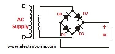
When the top end of transformer secondary is positive with respect to the bottom end, then we call it a positive half cycle. During this period diode D1 and D3 are forward biased, as a result there is a current flow which passes through D1, Rl, and D3 back to bottom end of secondary thereby passing that positive half cycle to the output. During this period D2 and D4 are reverse biased so there is no current flow through them. Now during the negative half cycle, diodes D2 and D4 are forward biased, so the current passes through D4, Rl and D2 back to secondary. During this process also, the current flow direction through Rl is same as through that in first case and so is the voltage drop. So again a positive half cycle is created at the output due to the negative half cycle at input. Hence we obtain two positive half cycles at the output due to a full cycle at the input. Hence this circuit is called a Full wave rectifier.
Wave forms

Specifications Of A Rectifier
- Peak Inverse Voltage :-
Peak inverse voltage is the maximum reverse voltage appearing across a single diode in a rectifier. Consider the positive half cycle when the output voltage reaches Vmax, D1 and D3 are conducting whereas diode D2 and D4 are reverse biased. In this case D1 and D3 have almost zero resistance. As a result the maximum reverse voltage appearing across D2 and D4 is equal to Vmax.
Therefore PIV = Vmax.
- Peak Current:-
Imax = Vmax/ ((2*Rf)+Rl);
Where Rf is the forward bias resistance of Diodes and Rl is the load resistance.
- Average value of current:-
Idc = (2*Imax)/ ∏
- Root Mean Square (RMS) value of current:-
Irms = Imax / (√2).
- Output frequency of Output = input frequency
- Rectifier efficiency = 81.2 %
- Ripple factor = .482
Ripple is the amount of AC component in output waveform.
Merits Of Bridge Rectifier over other rectifiers:-
- Lowcost
- High reliability
- PIV (bridge) = PIV (centre tappd) /2
- Smaller in size
- No special centre tapped transformer is required
Applications:-
- Simple Bridge Rectifier along with a shunt capacitor filter is usually used in Mobile Battery Chargers.
- Excessive applications in medium Load conditions.


oui … bien sûr … cette RECTIFER nous aide à surmonter les inconvénients de DC transmission.
Yes…….. ofcourse …
le AC peut-il être parfaitement redressé comme le DC des batteries?
thank u vivek V.S for ur valuable information…