

Interfacing Servo Motor with 8051 using Keil C
Contents
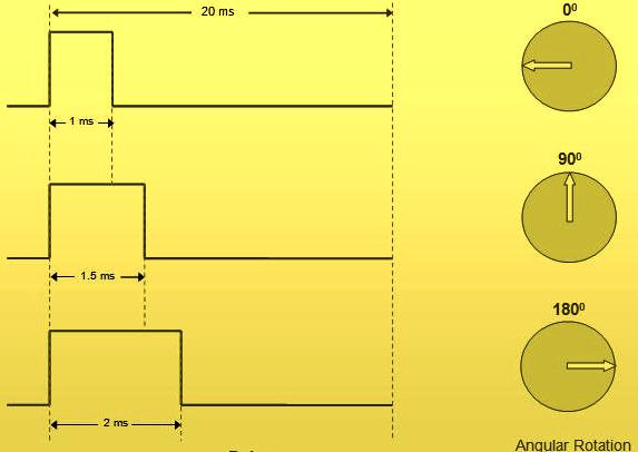
A servo motor uses servo mechanism, which is a closed loop mechanism that uses position feedback to control the precise angular position of the shaft. Stepper Motors, which is an open loop system can also be used for precise angular control. But Servo Motors are preferred in angular motion applications such as robotic arm. Moreover controlling of servo motors are very simple, easy and needs no extra hardware like stepper motor. Usually hobby circuit servo motors have three wires. Two of them are red and black which is used to give power to the motor and the third wire is used to provide control signal for angular position. It uses Pulse Width Modulated (PWM) waves as control signals. The angle of rotation is determined by the width of the pulse at the control pin. The servo motor used here is having angle of rotation from 0 to 180 degrees. We can control the exact angular position by varying the pulse between 1ms to 2ms. Before using this in your application, please refer the datasheet of your servo for angle and pulse width informations.
Circuit Diagram
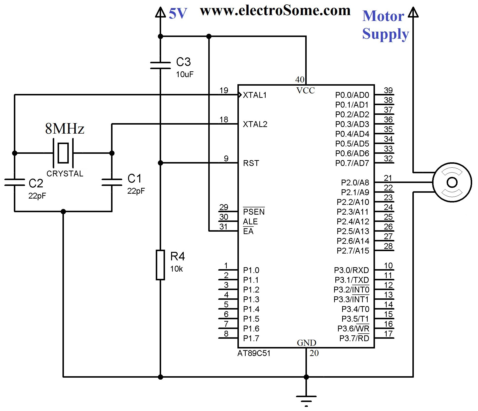
8MHz crystal is used to provide the required clock for 8051 microcontroller and 22pF capacitors are used to stabilize the operation of crystal. 10KΩ resistor and 10μF capacitor is used to provide the required Power On Reset (POR) to the microcontroller. Control of Servo Motor is connected to first pin of Port 2.
Keil C Code
#include<reg52.h>
#include<stdio.h>
#include <intrins.h>

sbit motor_pin = P2^0;
void Delay(unsigned int);
void Delay_servo(unsigned int);
void main()
{
  motor_pin = 0;

  do
  {
    //Turn to 0 degree
    motor_pin = 1;
    Delay_servo(50);
    motor_pin = 0;

    Delay(1000);

    //Turn to 90 degree
    motor_pin=1;
    Delay_servo(82);
    motor_pin=0;

    Delay(1000);
    //Turn to 180 degree
    motor_pin=1;
    Delay_servo(110);
    motor_pin=0;

    Delay(1000);
  }while(1);
}

void Delay(unsigned int ms)
{
  unsigned long int us = ms*1000;
  while(us--)
  {
    _nop_();
  }
}

void Delay_servo(unsigned int us)
{
  while(us--)
  {
    _nop_();
  }
}
Download Here
You can download Keil C files and Proteus files here…


now it’s working sir
how do we upload this code to the microcontroller
This code will work for at89s51?
Can this program work on AT89S52
Thanks for the feedback.
very good article, cleared all my concepts of controlling the servo by using PWM .The simulation worked very well on proteus. Now i hope i can control this hobby servos with industrial PLC.
Are you sure those connection were correct ? It won’t damage the servo even if you provide wrong signals from the microcontroller. Most probably you given motor power supply to the signal input terminal.
i tried this code in Tower Pro M G 90S micro servo and 89s52 controller,sadly my servo become very hot and now its not working,i tried the same thing on another servo…i lost that one tooo.. 🙁 plz help
That is calculated by trial and error.
hi
can you please explain delay calculation behind the figures 50 ,82 and 110
i mean what is the formula behind it
It will vary depending on the servo you are using. Best method is to use trial and error.
Hi sir! how to calculate the value xx?
You can change the pulse width by changing the delay.
by pulse width do you mean the values of “xx” in delay_servo(xx)??
Yes, ofcourse..
You may use switches or potentiometer to provide input signals..
hello sir
is it possible to contrl the pulse width externaly…..? if yes ….how?
Sorry, we haven’t assembly language code.
Hello sir..
sir i want coding of servo motor in assembly language that servo motor rotate in clockwise as well as anti-clockwise.
please guide me sir.
i will be thankul to you…
Just adjust the pulse width.. position will be updated accordingly..
how to control the position sir
Keil C
Which the compiler you used?
I use Sdcc, but it does not work with your code.
It is an instruction to “do nothing”… It simply waste time for 1 clock cycle…
_nop_ wat is it