

Interfacing Servo Motor with Atmega32 Microcontroller
Contents

Servo Motor is a DC Motor equipped with error sensing negative feedback to control the exact angular position of the shaft. Unlike DC Motors it will not rotate continuously. It is used to make angular rotations such as 0-90°, 0-180° etc. Stepper Motors can also be used for making precise angular rotations. But Servo Motors are preferred in angular motion applications like robotic arm, since controlling of servo motors are simple, needs no extra drivers like stepper motor and only angular motion is possible.
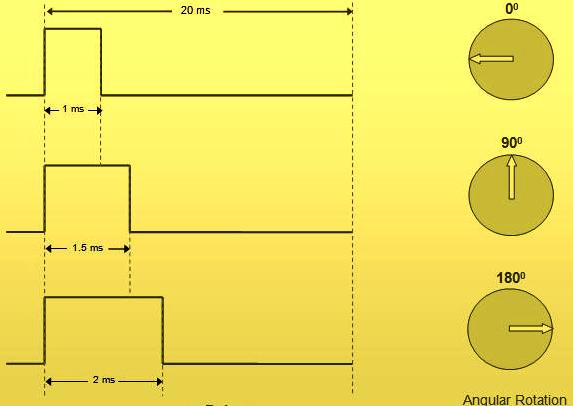
Operation of Hobby Servo Motor is very simple, it has only three wires, two of them (Red and Black) used to provide power and the third wire is used to provide control signals. Pulse Width Modulated (PWM) waves are used as control signals and the angular position is determined by the width of the pulse at the control input. In this tutorial we are using a servo motor having angle of rotation from 0-180° and angular position can be controlled by varying the pulse width between 1ms to 2ms.
Note : Please refer the datasheet of your Servo Motor, before using the program in this tutorial. Angular range and control pulse width are different for different servo motors.
Circuit Diagram

8 MHz Crystal is used to provide the required clock for Atmega32 Microcontroller and 22pF capacitors are used to stabilize the operation of the crystal. 10KΩ resistor and 10μF capacitor is used to provide the required Power On Reset (POR) to the microcontroller. Control of servo motor is connected to the first pin of PORTC (RC0), which is declared as an output pin in the program.
Program
#ifndef F_CPU
#define F_CPU 8000000UL // 8 MHz clock speed
#endif

#include <avr/io.h>
#include <util/delay.h>

int main(void)
{
  DDRC = 0x01; //Makes RC0 output pin
  PORTC = 0x00;
  while(1)
  {
    //Rotate Motor to 0 degree
    PORTC = 0x01;
    _delay_us(1000);
    PORTC = 0x00;

    _delay_ms(2000);

    //Rotate Motor to 90 degree
    PORTC = 0x01;
    _delay_us(1500);
    PORTC = 0x00;

    _delay_ms(2000);

    //Rotate Motor to 180 degree
    PORTC = 0x01;
    _delay_us(2000);
    PORTC = 0x00;

    _delay_ms(2000);
  }
}
Download Here
You can download Atmel Studio files and Proteus files here…


lol your F_CPU is set to 8 MHz and not 16 MHz