

Using Push Button Switch with PIC Microcontroller
Contents
Introduction
This article is meant for beginners in the field of microcontrollers. When I started with microcontrollers, as everyone I also need to learn how to interface a switch with microcontroller. Here we use PIC Microcontroller 16F877A and MikroC Pro compiler. This tutorial assumes you have basic knowledge about programming PIC Microcontroller, else you read the article Blinking LED using PIC Microcontroller.


In this tutorial we use a push button switch, when we press on it an LED glows for a second. Push Buttons are mechanical switches. Then can make or break connection between two terminals and comes back to stable state when released. They are called as Push to ON or Push to OFF switches respectively.
Circuit Diagram
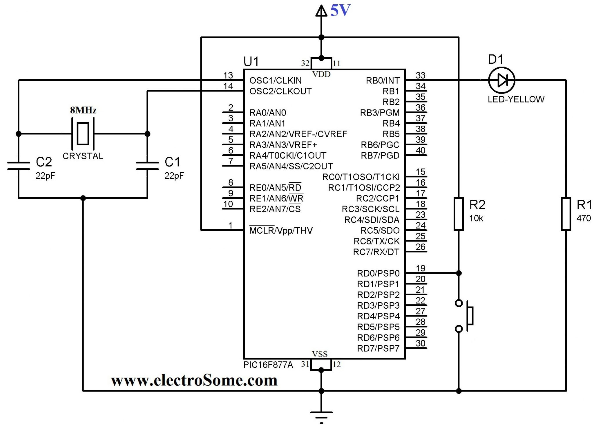
Note: VDD and VSS of the pic microcontroller is not shown in the circuit diagram. VDD should be connected to +5V and VSS to GND.
Push button switch is connected to the first bit of PORT D (RD0) which is configured as an input pin. Which is connected to a pull up resistor such that this pin is at Vcc potential when the switch is not pressed. When the switch is pressed this pin RD0 will be grounded. The LED is connected to the first bit of PORT B (RB0) and a resistor is connected in series with it to limit the current.
MikroC Program
void main()
{
  TRISD.F0 = 1; //Configure 1st bit of PORTD as input
  TRISB.F0 = 0; //Configure 1st bit of PORTB as output
  PORTB.F0 = 0; //LED OFF
  do
  {
    if(PORTD.F0 == 0)   //If the switch is pressed
    {
       Delay_ms(100);    //Switch Debounce
       if(PORTD.F0 == 0)//If the switch is still pressed
       {
         PORTB.F0 = 1; //LED ON
         Delay_ms(1000); //1 Second Delay
         PORTB.F0 = 0; //LED OFF
       }
    }
 }while(1);
}
In the above program you may noticed that the switch is checked twice with a 10 millisecond delay. This is to avoid invalid clicks by Switch Bouncing.


in that example he used pull up, the input received voltage from VCc, which make it 1,once the button pressed the input will become 0,that is why our boss instruct the machine that if(port of the input ==0),the port set to be output should be on.
(LED) = (~LED);
__delay_ms(100);
Above tutorial is not working properly. I was not able to control LED by switch , LED is glowing like blinking. can you please write the code for that?
hii sir, i want to program led as,
when i pressed 1st button then 1st led on.
when i pressed 2nd button then 1st led off,without realising the 1st button.
please sir tell me.
Better try some other PORTS. For PORTA you need to configure it as digital input first.
Don’t forget to configure TRIS register for setting whether a pin is Input/Output.
SIR.. PLZ HELP..
I have measured volt+out volt on lcd but ,,i want to measure one button …if i press the button ,then if(PORTA.RA3 == 1) //If the switch is pressed
{
Lcd_Out(2,1,”OVERLOAD “);
overload should be showed on lcd,,
//
my program
float inputread,inputread2, inputmeasured,inputmeasured2, in2,in;
// Lcd module connections start
sbit LCD_RS at RC7_bit;
sbit LCD_EN at RD4_bit;
sbit LCD_D4 at RD5_bit;
sbit LCD_D5 at RD6_bit;
sbit LCD_D6 at RD7_bit;
sbit LCD_D7 at RB3_bit;
sbit LCD_RS_Direction at TRISC7_bit;
sbit LCD_EN_Direction at TRISD4_bit;
sbit LCD_D4_Direction at TRISD5_bit;
sbit LCD_D5_Direction at TRISD6_bit;
sbit LCD_D6_Direction at TRISD7_bit;
sbit LCD_D7_Direction at TRISB3_bit;
char txt[9]; // declare a char array
char txt2[11]; // declare a char array
void main(){
TRISA.RA1=1; // PORTA is input
TRISA.RA2=1; // PORTA is input
TRISA.RA3=1;
TRISB=0; // PORTC is Output
TRISC=0; // PORTC is Output
ADC_Init(); // Initialize ADC module with default settings
Lcd_Init(); // Initialize Lcd
Lcd_Cmd(_LCD_CLEAR); // Clear display
Lcd_Cmd(_LCD_CURSOR_OFF); // Cursor off
Lcd_Out(1,7,”Welcome”); // dsiaplay the welcome logo on the LCD screen at position ROW=1 COLUMN=1
delay_ms(100); // keep displaying logo for 5s
Lcd_Cmd(_LCD_CLEAR); // Clear display
Lcd_Cmd(_LCD_CURSOR_OFF); // Cursor off
Lcd_Out(1,3,”Adam Ubaid”);
delay_ms(100); // keep displaying logo for 5s
while(1){
inputread = ADC_Read(1);
inputread2 = ADC_Read(2);// Read analog value from channel 0
delay_ms(5);
inputmeasured=(inputread*4.88)/1000; // converting to value
in = (inputmeasured/0.005);
inputmeasured2=(inputread2*4.88)/1000; // converting to value
in2 = (inputmeasured2/50000.0);
floatToStr(in,txt);
floatToStr(in2,txt2);
Lcd_Out(3,1,”PV Volts”);
lcd_out(3,12,txt);
Lcd_Out(4,1,”OUTPUT V “);
lcd_out(4,12,txt2);
if(PORTA.RA3 == 1) //If the switch is pressed
{
Lcd_Out(2,1,”OVERLOAD “);
}
} }
Hi sir..I want to interface 5 leds with 1 push button..plz help me!mail me
can help me draw PIC18F4550 AND CODE
MY QUESTION
exercise
Sw1 = led1 on,buz on
sw2 = led2 on,buz off
Hi, I have watched your tutorial on “Using Push Button Switch with PIC Microcontroller” and I am trying to make something similar, that is, output voltage “3.3V” if input is bigger than 1V using PIC24F16KL402. But initially I want to implement simple output voltage to turn an LED on. I’ve tried:
#include
#include
#include “trial.h”
#include
void main(void) {
TRISB = 0b00000000;
while(1){
PORTBbits.RB3 = 1;
}
}
But nothing is happening. I’m using mplab with pickit 3, everything seems to be fine, the code compiles and gets downloaded to the pic but not working.
Help! Thanks!
Hi Ligo
I loaded your schematic into proteus with the code and couldn’t get the simulation to run until I replaced the pull-up resistor with a simple diode.
I would like to use your example on a machine. It works like this:
1. I have to push 2 buttons together to get an input to the micro controller
2. Air cylinder 1 must move for a set time and then stop.
3 Air cylinder 2 must move for a set time and then stop.
4. Air cylinder 1 must continue.
5. Air cylinder 3 must move for a set time and then stop.
6. Air cylinder 1 must return to home position.
Am I able to do this or is there a better way?
thankyou in advance
John
Whe user TRISD.F0
INSTEAD OF TRISD.RD0?
Kindly describe your applicaiton.
Please use our forums ( https://electrosome.com/forums/ ) for asking doubts outside the scope of above article.
sir, i want to do control two led with use one push button only.
can u help me?
You can easily do it if you understand above tutorial.
hi sir
i want to do on the led when switch is pushed.
if the same switch is again pushed then led will be turned off
for that ques u replied like
led = off
if(switch on)
{
led = !led (! = not)
}
can pls tell me exact code..
You may use interrupt feature or just a simple counter.
Excuse me.
How could I write a code of an example below:
-single click PB0 => PD0=1 /LED1 ON/
-double click PB0 => PD1=1 /LED2 ON/
Thanks in advanced.
Sorry, I don’t understand your project.
Please use our forums ( https://electrosome.com/forums ) for asking such questions.
May i know how to make PIC16F877A coding to select different location of city?
how to select different location of city by using switch button in pic16f877A microC?
anyone can help me please??
hello sir , i need your help, i need if i press switch (switch1), LED should be On. If again press and hold same switch(switch1),other LED should be On state, please its urgent , can you send me the code please sir
You an use variable delay functions in MikroC. Just connect a potentiometer and read its value using ADC.
How to control blinking speed of led using analogue channel of pic micro
How to
I think the program is correct.
Sir, im trying to implement a logic where button1 when pressed sets a pin x to 1 and clears pin y to 0. button 2 when pressed sets pin y to 1 and clears pin x. i can get one setting but the other button cannot set its pin , it only clears the other pin. plz help. heres my code.
void main() {
TRISD.F6=1;
TRISD.F2=0;
TRISD.F5=1;
TRISD.F3=0;
TRISD.F4=1;
TRISC.F4=0;
while(1){
if(PORTD.F6==0 ) //If the switch is pressed
{
Delay_ms(100); //Switch Debounce
if(PORTD.F6==0)//If the switch is still pressed
{
PORTD.F2 = 1; //LED ON
PORTD.F3=0; // turn off others
}
}
if(PORTD.F5==0 ) //If the switch is pressed
{
Delay_ms(100); //Switch Debounce
if(PORTD.F5==0)//If the switch is still pressed
{
PORTD.F2=0; // turn off others
PORTD.F3 = 1; //LED ON
}
}
}
}
It is very simple. You can do it yourself if you understand above program.
hello sir i need to switch on led only when a switch is released after press…
It will work without any problems.
The above project is 100% working.
Sorry, it works but I could not understand why LED turns on when the press is not pressed even if the code tells the inverse?
It does not work. LED turns on even if the button is not pressed!
same thing by ccs copmpiler..
and thnks in advance
try like this :
if(SWITCH PRESS)
{
LED = !LED;
}
Hello sir i tried this and i got the led off when the switch is released. When the switch is pressed the led is on and when released its off. But actually what I want is to make the led on on single press and release and the state must be saved and off only when there is another switch press. So can you give me some idea. I have tried many things but not working. Thanks for the help
try like this :
t = 0;
if(SWITCH PRESSED)
{
LED = ON;
while(t < constant)
{
if(SWITCH PRESSED)
{
LED = OFF;
break;
}
DELAY;
t++;
}
}
iam sorry but could you help me
i want to turn on a led by pressing on a switch and wont turn off till a minute is passed or the by pressing on the same switch
Sorry we don’t have such program…
You should program it yourself.. Commenting section is to ask doubts about above article..
Please use our forums : https://electrosome.com/forums for asking doubts not related to above article.
can i have program using four switches to display four different status on lcd pic 16f877a
I hope that your problem is already solved here :
https://electrosome.com/topic/pic16f877a-push-button/
Hi Ligo George..,
I need your help am working on pic16f877a and using XC8 complier. Have interfaced pushbutton if I press the button value should increment.. its working fine but one more condition – if I keep press and hold down for long time fastely value should increment how to do this I dont no am trying but not achieved. Below is my button code
void main()
{
int oldstate;
oldstate = 0;
while(1)
{
if(RA4 == 1) // switch
{
oldstate = 1; // update flag
}
if(oldstate &&(RA4 == 0))
{
val++;
if(val > 10)
{
val = 1;
}
oldstate = 0; // update flag
}
}
which type of configuration bits i got to set ???
thanks.
is there any errors in my codes as i put it above???
please check my codes.
thanks.
Please use our forums (https://electrosome.com/forums) for asking doubts which are not related to above topic.
can any one tell the logic used in the main function?i mean plz explain if u understand
/* Interfacing 4-digit 7-segment display
This program implements time-multiplexed 4-digit 7-segment
display interfacing of type common anode. PORT A (pin 2 to 5) and
PORT B are used for digit selection and segement lines, respectively.
Author M Tahir
Date Nov 25, 2013
*/
#define SYSCTL_RCGC2_R (*((volatile unsigned long *)0x400FE108))
#define GPIO_PORTA_DATA_R (*((volatile unsigned long *)0x400043FC))
#define GPIO_PORTB_DATA_R (*((volatile unsigned long *)0x400053FC))
#define GPIO_PORTF_DATA_R (*((volatile unsigned long *)0x40025040))
#define GPIO_PORTA_DIR_R (*((volatile unsigned long *)0x40004400))
#define GPIO_PORTB_DIR_R (*((volatile unsigned long *)0x40005400))
#define GPIO_PORTA_DEN_R (*((volatile unsigned long *)0x4000451C))
#define GPIO_PORTB_DEN_R (*((volatile unsigned long *)0x4000551C))
#define GPIO_PORTF_DEN_R (*((volatile unsigned long *)0x4002551C))
#define GPIO_PORTF_PUR_R (*((volatile unsigned long *)0x40025510))
#define SYSCTL_RCGC2_GPIOABF 0x00000023 //Port A,B,F Clock Gating Control
#define PORT_A_PINS 0x3C // Port A pins 2,3,4 and 5
#define DEALY_COUNT 10000
void Delay(unsigned long counter);
void Port_Init(void);
// Global variable declarations
unsigned char Lookup_7Seg_Disp[10] = {0xC0, 0xF9, 0xA4, 0xB0, 0x99, 0x92, 0x82, 0xF8, 0x80, 0x90};
unsigned char i, count=0, flag=0;
int main()
{
// Initialize the ports
Port_Init();
while(1)
{
for(i = 1; i <= 4; i++)
{
GPIO_PORTB_DATA_R = Lookup_7Seg_Disp[i+count];
// Select the digit on Port A
GPIO_PORTA_DATA_R = (PORT_A_PINS – (1 < 5)
count = 0;
Delay(DEALY_COUNT);
}
}
else
{
flag = 0;
}
}
}
// Intialization routine for setting up the required ports
void Port_Init()
{
// Enable the clock for port A, B and F
SYSCTL_RCGC2_R |= SYSCTL_RCGC2_GPIOABF;
// Configure Port A and B direction and digital enable functions
GPIO_PORTB_DIR_R = 0xFF;
GPIO_PORTB_DEN_R = 0xFF;
GPIO_PORTA_DIR_R = PORT_A_PINS;
GPIO_PORTA_DEN_R = PORT_A_PINS;
// Configure port F as digital input with pullup
GPIO_PORTF_DEN_R |= 0x10; // enable digital I/O on PF4
GPIO_PORTF_PUR_R |= 0x10; // enable weak pull-up on PF4
// Make port A and B logic high so all the LEDs are OFF.
GPIO_PORTA_DATA_R = PORT_A_PINS;
GPIO_PORTB_DATA_R = 0xFF;
}
// This function implements the delay
void Delay(unsigned long counter)
{
unsigned long i = 0;
for(i=0; i< counter; i++);
}
r u talking about mine code or ur code??????
The codes given in this article will work on Proteus without any problem. But when using in hardware you should make sure that configuration bits are correct.
i tried mine codes but not succeed.and i want to use portb as input and want to use interrupt service routine.
thanks.
You can use the same code in Proteus 8.
hi.
i am using Proteus 8, hi tech compiler.
thanks.
pl give example pl .
You can use a variable to count the switch pressing.
Please use our forums : https://electrosome.com/forums for asking doubts outside the scope of above article. Also elaborate your question.
hi i want to do on-off the led one by one If the switch is unpressed.its i call Task_1. it work fine .those are
as
void Task_1()
{
if(PORTD.F0 == 1)//If the switch is unpressed . its free runing code
{
PORTB.F0 = 1; //LED ON
Delay_ms(1000); //1 Second Delay
PORTB.F0 = 0; //LED OFF
PORTB.F1 = 1; //LED ON
Delay_ms(1000); //1 Second Delay
PORTB.F1 = 0; //LED OFF
PORTB.F2 = 1; //LED ON
Delay_ms(1000); //1 Second Delay
PORTB.F2 = 0; //LED OFF
PORTB.F3 = 1; //LED ON
Delay_ms(1000); //1 Second Delay
PORTB.F3 = 0; //LED OFF
}}
now i want to modified code as, if switch is pressed 1 time PORTB.F0 = 1; LED on-off till 20sec , if agen
pressed PORTB.F1 = 1; LED on-off till 25sec ,if agen pressed PORTB.F2 = 1; LED on-off till 30sec , if agen
pressed PORTB.F3 = 1; LED on-off till 25sec . Switch Debounce time is 100 ms , its i call Task_2
if switch is pressed more then Switch Debounce time , mcu extit Task_2
so now code is
void Task_2()
{
if(PORTD.F0 == 0) //If the switch is pressed 1 time
{
Delay_ms(100); //Switch Debounce
if(PORTD.F0 == 0)//If the switch is still pressed
{
PORTB.F0 = 1; //LED ON
Delay_ms(1000); //1 Second Delay
PORTB.F0 = 0; //LED OFF
}
}}
for 2nd time whats need ? ?
Can you please help….?
sir,,
can you please show me a coding for 8 led and 4 push button,,
and the led will only light up when push 2 button,,
hope you can help me as soon as possible,,
need this for my assignment,,
Which compiler you are using ? If your doubt is not related to above article.. please open a new topic in our forums.. ( https://electrosome.com/forums )
int main()
{
TRISB0 = 0; //RB0 as Output PIN
TRISD0 = 1; //RD0 as Input PIN
RB0 = 0; //LED Off
while(1)
{
if(RD0 == 0) //If Switch Pressed
{
RB0 = !RB0;
__delay_ms(300);
}
}
return 0;
}
You can use a transistor driver to drive 50 LEDs from mains.. You may also use a capacitor based transformer less power supply for PIC..
hi sorry to disturb u …
i need help with this program.
it doesnt work on hardware..
///////////////////////////////////////////////////////////////////////////
#include
#define _XTAL_FREQ 4000000
void main()
{
TRISD=0b00000000;
TRISB=0xf0;
PORTD=0b00000000;
INTEDG=0;
ANSEL=0x00;
ANSELH=0x00;
RBIE=1;
GIE=1;
IOCB=0xff;
while(1)
{
//PORTD=0b11111111;
}
}
void static interrupt isr()
{
char c;
if(RBIF==1)
{
RBIE=0;
GIE=0;
//c=PORTB;
{
PORTD=!PORTD;
}
GIE=1;
RBIF=0;
INTF==0;
}
}
hi
could u plz tell me in c language as i do programming in mp lab…c language.
thanks
hi !!!
how to connect more than 50 leds with pic micro controler and ac power ??????????
please help me.
thanks.
thank u!
Sorry, please use our forums ( https://electrosome.com/forums )if you need support outside the scope of above tutorial
It will work without any problem if you are using above code and circuit..
thanks!can u give some logic for this?
This code is running perfectly in proteus, but with same code when i try in real hardware the led start blinking itself without button pushed, please help me if there is bother with ADC ? i am using pic16f877a
thankssssssss
You may use timer module of PIC or.. you can use a variable for checking time which is incremented on every iteration of the loop..
Just use a variable to count it… and you can convert that variable in to string using IntToStr() mikroc function…. and you can print it on the LCD
how to count the number of input that is switch using every 1s and display it in lcd!!
hi! what is the program when i press abutton,how much i press button and display in lcd!!
Hi,
How can I coding,
when 1st switch press 1st led on and 2nd led off. again 1st switch press 1st led off and 2nd led on.
When 2nd switch press 1st led on and 3rd led off. again 2nd switch press 1st led off and 3rd led on.
void main()
{
TRISD.F0 = 1; //Configure 1st bit of PORTD as input
TRISB.F0 = 0; //Configure 1st bit of PORTB as output
PORTB.F0 = 0; //LED OFF
do
{
if(PORTD.F0 == 0) //If the switch is pressed
{
Delay_ms(100); //Switch Debounce
if(PORTD.F0 == 0)//If the switch is still pressed
{
PORTB.F0 = !PORTB.F0;
}
}
}while(1);
}
hi. i want to do a task. if push button is pressed once the led wants to turn on. again if the switch is pressed the led wants to turn off. plz help me
🙂
okay now i understand thank you so much .
while(1) >> while(TRUE)…. makes INFINITE LOOP… It will run the program as far the power is given to microcontroller..
Why we using while(1) ?
Ligo Thankyou so much, its very help full to me.
Try changing 0 to 1 :
if(PORTC.F6== 1) //If the switch is pressed
{
Delay_ms(100); //Switch Debounce
if(PORTC.F6 == 1)//If the switch is still pressed
void main()
{
TRISC.F6 = 1; //Configure 1st bit of PORTD as input
TRISB.F6 = 0; //Configure 1st bit of PORTB as output
PORTB.F6 = 0; //LED OFF
do
{
if(PORTC.F6== 0) //If the switch is pressed
{
Delay_ms(100); //Switch Debounce
if(PORTC.F6 == 0)//If the switch is still pressed
{
PORTB.F6 = 1; //LED ON
Delay_ms(1000); //1 Second Delay
PORTB.F6 = 0; //LED OFF
}
}
}while(1);
}
when i write this the led is already on and when i push the button it turns off what is wrong with my program
like this :
…
…
while(switch pressed); //Waits for switch release
Relay 1 OFF;
Relay 2 ON
…
…
Visit this page : http://electrosome.com/hc-sr04-ultrasonic-sensor-pic/
There is a sample code.
can you explain further it can i see i sample code thank you ligo 🙂
Yes, you can do it by simply writing to PORT register.
Try this article : http://electrosome.com/hc-sr04-ultrasonic-sensor-pic/
it uses PORTB On Change Interrupt.
and hoe do I use the PORTB on change interrupt? sorry for questions I’m a beginner in using PIC thank you for the concern
thank you but my concern is when the button is released then the relay1 is off and the relay2 is on what do you think about this? thank you for your reply
Try like this :
if(switch pressed)
Relay 1 ON
while(switch pressed); // LOOP HERE
Relay 1 OFF
Relay 2 ON
Better solution is to use PORTB On Change Interrupt.
hello! can i have an idea about the program for this situtation;
when the button is pressed, the port connected to relay1 will go high, then when the button is released the the port connected to relay2 will go high while the port in relay1 will turn low and after the buttton is still release the port will go off.
can you help me with this?
thank you!
Thank u,
How can i do coding when button press 1st led on, again press 2nd led on 1st led off, again press 3rd led on 1st and 2nd led off,
just drop a mail to [email protected] or use Contact Us Page..
how can i premium support..
Hello, you can use PIC’s ADC for that..
You asking questions which are out of our scope…. This commenting system is only intended to ask doubts related to above article….
If you wan’t premium support you need to hire one of our engineers. ..
Thank u Ligo George
How to coding for battery with 4 led, when battery 12v 1st led on other off, after battery 11v than 2nd led on other led off, again battery 10v 3rd led on and other led off, again battery 9v 4led on other led off,
Try like this …
void main()
{
char cnt;
cnt = 0;
while(1)
{
if(switch pressed)
cnt++;
if(cnt == 1)
{
//action here
}
else if(cnt == 2)
{
//action here
}
}
}
Try this :
void main()
{
TRISD.F0 = 1; //Configure 1st bit of PORTD as input
TRISD.F1 = 1;
TRISB.F0 = 0; //Configure 1st bit of PORTB as output
TRISB.F1 = 0;
PORTB.F0 = 0; //LED OFF
do
{
// LED 1
if(PORTD.F0 == 0) //If the switch is pressed
{
Delay_ms(10); //Switch Debounce
if(PORTD.F0 == 0)//If the switch is still pressed
{
PORTB.F0 = !PORTB.F0; // LED out port
}
}
Delay_ms(10); // LED Delay
// LED 2
if(PORTD.F1 == 0) //If the switch is pressed
{
Delay_ms(10); //Switch Debounce
if(PORTD.F1 == 0)//If the switch is still pressed
{
PORTB.F1 = !PORTB.F1; // LED out port
}
}
Delay_ms(10); // LED Delay
}while(1);
}
1st switch working but 2nd switch not working. here is code
void main()
{
TRISD.F0 = 1; //Configure 1st bit of PORTD as input
TRISB.F0 = 0; //Configure 1st bit of PORTB as output
PORTB.F0 = 0; //LED OFF
do
{
// LED 1
if(PORTD.F0 == 0) //If the switch is pressed
{
Delay_ms(10); //Switch Debounce
if(PORTD.F0 == 0)//If the switch is still pressed
{
PORTB.F0 = !PORTB.F0; // LED out port
}
}
Delay_ms(10); // LED Delay
// LED 2
if(PORTD.F1 == 0) //If the switch is pressed
{
Delay_ms(10); //Switch Debounce
if(PORTD.F1 == 0)//If the switch is still pressed
{
PORTB.F1 = !PORTB.F1; // LED out port
}
}
Delay_ms(10); // LED Delay
}while(1);
}
Hi. How can I use the same button to change the pattern of the blinking of the led? for example;
Button’s 1st press: the led will turn on and stays on
Button’s 2nd press: the led will blink 5 times
Button’s 3rd press: the led will blink 3 times
I can’t seem to get it to work using the same button. Thanks in advance!
1st switch working but 2nd switch not working. here is code
void main()
{
TRISD.F0 = 1; //Configure 1st bit of PORTD as input
TRISB.F0 = 0; //Configure 1st bit of PORTB as output
PORTB.F0 = 0; //LED OFF
do
{
// LED 1
if(PORTD.F0 == 0) //If the switch is pressed
{
Delay_ms(10); //Switch Debounce
if(PORTD.F0 == 0)//If the switch is still pressed
{
PORTB.F0 = !PORTB.F0; // LED out port
}
}
Delay_ms(10); // LED Delay
// LED 2
if(PORTD.F1 == 0) //If the switch is pressed
{
Delay_ms(10); //Switch Debounce
if(PORTD.F1 == 0)//If the switch is still pressed
{
PORTB.F1 = !PORTB.F1; // LED out port
}
}
Delay_ms(10); // LED Delay
}while(1);
}
Hello, use GPIO instead of PORTB, PORTD etc.. and TRISIO instead of TRISB, TRISD etc..
Try this logic :
if(switch 1 pressed)
{
LED 1 ON;
}
if(switch 2 pressed)
{
LED 2 ON;
}
Do you kindly give some example how to configure PIC12F675 8 pin microcontroller I/Os in micro c
how can i do coding mikroc when 1st switch press 1st led on and 2nd switch press 2nd led on?
Thank you it’s working,
and now how can coding fast switch press fast led on, and 2nd switch press 2nd led on.
Try this :
void main()
{
TRISD.F0 = 1; //Configure 1st bit of PORTD as input
TRISB.F0 = 0; //Configure 1st bit of PORTB as output
PORTB.F0 = 0; //LED OFF
do
{
if(PORTD.F0 == 0) //If the switch is pressed
{
Delay_ms(100); //Switch Debounce
if(PORTD.F0 == 0)//If the switch is still pressed
{
PORTB.F0 = !PORTB.F0;
}
}
Delay_ms(200);
}while(1);
}
not working hare code:
void main()
{
TRISD.F0 = 1; //Configure 1st bit of PORTD as input
TRISB.F0 = 0; //Configure 1st bit of PORTB as output
PORTB.F0 = 0; //LED OFF
do
{
if(PORTD.F0 == 0) //If the switch is pressed
{
Delay_ms(10); //Switch Debounce
if(PORTD.F0 == 0)//If the switch is still pressed
{
PORTB.F0 = !PORTB.F0;
}
}
}while(1);
}
do like this :
if(switch pressed)
{
PORTB.F0 = !PORTB.F0;
}
hear is push button switch when press led on and automatic off.
how can i do coding mikroc when push button press led on and again press push button led off.
Hello George.. I need help that might be a different switch debouncing. I need to press a key and hold it for 3 seconds to enter in some type o programming mode. “lets say, turn ON an LED, or change some variable value” After I entered I should press and hold the key again for 3 seconds to exit.. If I use the same explanation for deboucing with more delay can Will that work safely?
Yes..
try this logic
led = off
if(switch on)
{
led = !led (! = not)
}
hi i want to do on the led when switch is pushed.
if the same switch is again pushed then led will be turned off..please help.
Can you please help….?
hi i want to do on the led when switch is pushed.
if the same switch is again pushed then led will be turned off..please help.
helo can u help..
Could please give me some codes for the tuning lights.
i want to trigger vibrating wire sensor by using a square wave with the interval 1 to 2 ms provide me a code because my code is not working properly
Thanks for the feedback..
thank you ligo now my code is working
i am working hard but still i cant done, my last code i share here please help me for button and lcd interfacing in 16g877a in micro c
// LCD module connections
sbit LCD_RS at RB4_bit;
sbit LCD_EN at RB5_bit;
sbit LCD_D4 at RB0_bit;
sbit LCD_D5 at RB1_bit;
sbit LCD_D6 at RB2_bit;
sbit LCD_D7 at RB3_bit;
sbit LCD_RS_Direction at TRISB4_bit;
sbit LCD_EN_Direction at TRISB5_bit;
sbit LCD_D4_Direction at TRISB0_bit;
sbit LCD_D5_Direction at TRISB1_bit;
sbit LCD_D6_Direction at TRISB2_bit;
sbit LCD_D7_Direction at TRISB3_bit;
// End LCD module connections
char txt1[] = “BEST”;
char txt2[] = “WAY”;
char txt3[] = “FOR”;
char txt4[] = “Learning”;
char i; // Loop variable
void Move_Delay() { // Function used for text moving
Delay_ms(500); // You can change the moving speed here
}
void main(){ // Configure AN pins as digital I/O
ADCON1 = 7;
// Disable comparators
CMCON = 7;
Lcd_Init(); // Initialize LCD
TRISA = 0xFF;
do
{
if(PORTA.F0 == 0)
{ Lcd_Cmd(_LCD_CLEAR); // Clear display
Lcd_Cmd(_LCD_CURSOR_OFF); // Cursor off
Lcd_Out(1,6,txt3); // Write text in first row
i=i+1;
delay_ms(5);
}
if ( PORTA.F1 == 0)
{
Lcd_Cmd(_LCD_CLEAR); // Clear display
Lcd_Cmd(_LCD_CURSOR_OFF); // Cursor off
Lcd_Out(1,6,txt2); // Write text in first row
Delay_ms(10);
}
}
while(1);
}
Refer this : http://electrosome.com/automatic-power-factor-controller-using-microcontroller/
and try searching on google…
Please don’t ask us to develop complete code for you…. we have no time for that… We will only provide support for projects in our site…
Try after disabling the adc.. .and configure pin PORTA.F0 as digital input by writing to ADCON registers… if you are using PIC16F877A..
hello sir i want to know about the programming of power factor correction using atmega 16 plz tell me the code how can i make thus projects
// LCD module connections
sbit LCD_RS at RB4_bit;
sbit LCD_EN at RB5_bit;
sbit LCD_D4 at RB0_bit;
sbit LCD_D5 at RB1_bit;
sbit LCD_D6 at RB2_bit;
sbit LCD_D7 at RB3_bit;
sbit LCD_RS_Direction at TRISB4_bit;
sbit LCD_EN_Direction at TRISB5_bit;
sbit LCD_D4_Direction at TRISB0_bit;
sbit LCD_D5_Direction at TRISB1_bit;
sbit LCD_D6_Direction at TRISB2_bit;
sbit LCD_D7_Direction at TRISB3_bit;
// End LCD module connections
char txt1[] = “BEST”;
char txt2[] = “WAY”;
char txt3[] = “FOR”;
char txt4[] = “Learning”;
char i; // Loop variable
void Move_Delay() { // Function used for text moving
Delay_ms(500); // You can change the moving speed here
}
void main(){
// ANSEL = 0; // Configure AN pins as digital I/O
// ANSELH = 0;
// C1ON_bit = 0; // Disable comparators
// C2ON_bit = 0;
Lcd_Init(); // Initialize LCD
// Lcd_Cmd(_LCD_CLEAR); // Clear display
// Lcd_Cmd(_LCD_CURSOR_OFF); // Cursor off
// Lcd_Out(1,6,txt3); // Write text in first row
// Lcd_Out(2,6,txt4); // Write text in second row
// Delay_ms(2000);
// Moving text
i = 0;
PORTA = 0;
//LCD_Config(&PORTD,1,0,2,7,6,5,4);
// PORTB = 0;
TRISA = 0x00;
do
{
if(PORTA.F0 == 0)
{ Lcd_Cmd(_LCD_CLEAR); // Clear display
Lcd_Cmd(_LCD_CURSOR_OFF); // Cursor off
Lcd_Out(1,6,txt3); // Write text in first row
i=i+1;
delay_ms(50);
}
if ( PORTA.F1 == 0)
{
Lcd_Cmd(_LCD_CLEAR); // Clear display
Lcd_Cmd(_LCD_CURSOR_OFF); // Cursor off
Lcd_Out(1,6,txt2); // Write text in first row
Delay_ms(100);
}
}
while(1);
}
this code interfacing button with LCD in micro C but not working please tell me what the problem in my code
MOTOR and SOLENOID is turned on in the if clause … but it is not turned off anywhere except at the beginning…
if i use a timer for 30 second to switch on led 6&7….is there any way that i can turn on led before the timer times up….
here is my command
void main() {
TRISB.F0 = 1;//THERMISTOR
TRISB.F1 = 1;//SWITCH MANUAL
TRISB.F6 = 0;//MOTOR
TRISB.F7 = 0;//SOLENOID
PORTB.F6 = 0;//INITIAL STATE MOTOR
PORTB.F7 = 0;//INITIAL STATE SOLENOID
do
{
if(PORTB.F0==0)
{
PORTB.F6 = 1; //ON AFTER 5 SECOND
PORTB.F7 = 1;
}
if(PORTB.F1==0)
{
delay_ms(30000);
PORTB.F6 = 1;//RELAY MOTOR ON
PORTB.F7 = 1;//RELAY SOLENOID ON
}
}while(1);
}
If the circuit diagram and program are correct .. it should work.. ..
Try using the hex file and circuit diagram provided by us..
.. Try changing your crystal..
pic detected….but blinking led not working 🙁
Did your programmer detect the pic??
if yes try blinking led..
excuse me sir… how do i know whether my picbroken or not….because i just bought it and test above code on a breadboard…the pic also didnt work on pic kit
Yes….use 5V for pic and use 24V for relay…
yeah thanks man….do i have to add another power supply if i wanna use 24v 5pin relay in this circuit??
yes.. you can add it…
if(PORTD.F0 == 0)
{
PORTB.F0 = 1;
}
if(PORTD.F1 == 0)
{
PORTB.F0 = 0;
}
i’ve make a little adjustment to your circuit…i disable the switch debounce function… can u add another push button on RD1 to switch off the led….im using mikroC
To write program to pic microcontroller you need a pic programmer..
Hi, I have a doubt in LCD interfacing,I have connected PIC16f877a and LCD in breadboard,how can i give a power supply to breadboard and also how to dumb my code in to PIC.
Then it is simple try control the motor using L293D..
http://www.electrosome.com/dc-motor-l293d-pic-microcontroller/
if(switch pressed)
{
rotate motor 1 clockwise;
Delay .. use the required delay here..
rotate motor 1 anti-clockwise..
Delay
rotate motor 2 clockwise
Delay
rotate motor 2 anti-clockwise
Delay.
…
….
..
}
changing of idea here,ignore the degree of rotation..i just want it to rotate clockwise and anticlockwise automatically.
for this time,im using a 12v dc motor .i do this project is just only to proof the concept ..can u help me in doing the coding and circuit?i need to use PIC too..
If you want to control exact degree.. then use servo motor or stepper motor………. If the application requires good torque use stepper motor… the programming and circuit will depends on the type of motor you are using…
Hi..i need some help here. im doing a project that need to move 3 motors move 180 degree back and forth in sequence with delay time of 5 seconds each using PIC.this project need only one switch to operate. when the switch is pressed,the first motor will rotate 180 degree back and forth.after the first motor back to its original position,the second motor will operate same as the first motor.same goes to the third motor.the operation stop when the third motor back to its original position.
i need help on circuit diagram as well as coding that can be use in proteus software.
I don’t get your question… can you please elaborate…??
how do i use Button in Miscellaneous lib??
Please Read this article : http://www.electrosome.com/stepper-motor-pic-microcontroller/
You should make some changes in the program…. in PIC18F4550 when you write output to a pin use LAT register, eg: LAT.F0 = 1; and use PORT register to read data from it, eg: if(PORTD.F0 == 1)…. and use TRIS register to write direction…
Adjust the delay between stepping to control the speed of the stepper motor..
thank you so much.Can you help me for stepper motor project??? I want to do project based on stepper motor with speed increment and decrement switch using pic 18f4550.
Please give reply.Thank you.
Thanks man
Very helpful. Thanks man
F0 denotes the first pin of PORTB …… F1 denotes second pin…
PORT register determines the logic level on a pin… while TRIS register determines whether a pin is input or output…
In the line PORTB.F0 what it denotes .f0?