

Generating PWM with PIC Microcontroller using Hi-Tech C
Contents
PWM (Pulse Width Modulation) is a powerful technique used to generate analog voltage using digital signals. It has a wide variety of applications such as controlling average power delivered to a load, generating analog voltage level, sine wave generation and DC Motor speed control. PWM signals are ON-OFF signals (hence the name Pulse) whose ON duration are changed (hence Width Modulation) according to our requirements. The fraction of time period for which the signal is ON to total time period is termed as Duty Cycle.
CCP Modules are available with a number of PIC Microcontrollers which can be used to generate PWM waves. CCP Stands for Capture/Compare/PWM. For programming this module in Hi-Tech C we should require a good hardware knowledge. Here for demonstration we are using PIC 16F877A.
CCP – Capture/Compare/PWM Modules
PIC 16F877A has two CCP modules named as CCP1 and CCP2. Each CCP Module has a 16 Bit register which can operate as :
- 16 Bit Capture Register
- 16 Bit Compare Register
- PWM Duty Cycle Register
This article deals only with PWM operation of CCP Modules. It can produce up to 10-bit resolution PWM output. Since CCP1 and CCP2 output are multiplexed with PORTC (RC2 and RC1), TRIS<2> and TRIS<1> must be cleared to make these pins output. CCP1 and CCP2 modules are similar in operation and you cannot set different frequencies for them, because both modules uses Timer 2 for their operation.
Working
The simplified block diagram of CCP module in PWM mode is shown below.
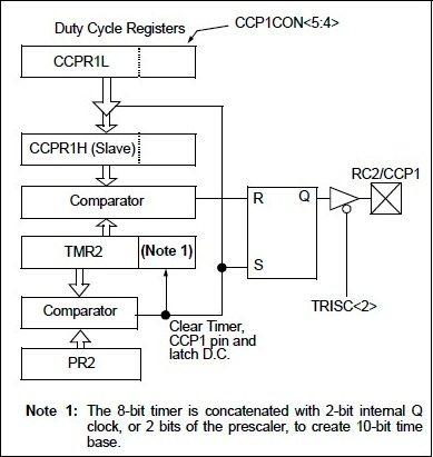
CCP modules uses Timer 2 for their operation. Period of the generated PWM waves is determined by the value in the PR2 register. Values of Timer 2 and PR2 are compared every-time using a comparator. When these values become equal, Timer 2 will be reset and output will become HIGH.
Duty cycle is determined by the value in CCPR1L and CCP1CON<5:4>. These registers can be written any time. So to avoid glitches in the PWM output, this duty cycle value is latched to CCPR1H and a 2 bit internal latch when there is a match between Timer 2 and PR2.
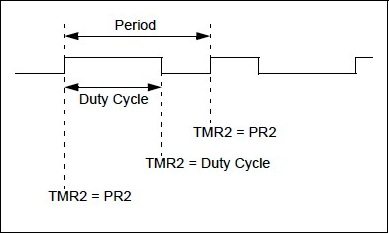
Then the value in CCPR1H and 2 bit internal latch is compared with Timer 2. When a match occurs output will become LOW as shown in the above diagram.
Note : The value of Duty Cycle value should not be greater than Time Period (PR2) value, if so the CCP pin will not be cleared.
The PWM resolution can be find using the following equation.

The following steps should be taken while configuring the PIC CCP module for PWM operation.
- Set the PWM Period by writing to the PR2 register and the PWM period can be calculated using the following equation.

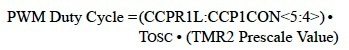
- Set the Duty Cycle of the PWM by writing to CCPR1L register and CCP1CON<5:4>. The PWM Duty Cycle can be find using the following equation and it should not exceed the PWM Period.

- Make CCP pins output by clearing the corresponding TRIS register bits.
- Set the Timer 2 (TMR2) prescale value and enable the timer by writing to T2CON register.
- Then configure the CCP module for PWM operation.
Circuit Diagram
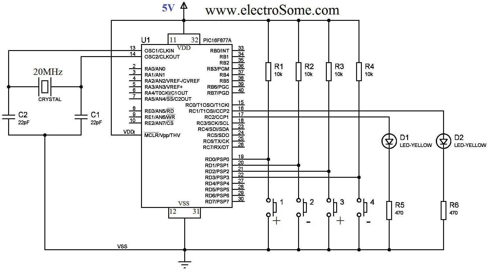
The above circuit diagram can be used for demonstrate the working of CCP modules in PWM mode. A 20MHz crystal is used for providing the necessary clock for the operation of the microcontroller and 22pF capacitors are used to stabilize the operation of crystal. Outputs of CCP1 and CCP2 modules are connected to LEDs using a series resistor to limit current. Four Switches are used to vary the duty cycle of the PWM waves. 10Ω resistors are used to Pull Up the inputs pins of microcontroller used for reading switches, when the switch is not ON.
Hi-Tech C Code
#include<htc.h>

#define _XTAL_FREQ 20000000
#define TMR2PRESCALE 4
long freq;

int PWM_Max_Duty()
{
  return(_XTAL_FREQ/(freq*TMR2PRESCALE);
}

PWM1_Init(long fre)
{
  PR2 = (_XTAL_FREQ/(fre*4*TMR2PRESCALE)) - 1;
  freq = fre;
}

PWM2_Init(long fre)
{
  PR2 = (_XTAL_FREQ/(fre*4*TMR2PRESCALE)) - 1;
  freq = fre;
}

PWM1_Duty(unsigned int duty)
{
  if(duty<1024)
  {
    duty = ((float)duty/1023)*PWM_Max_Duty();
    CCP1X = duty & 2;
    CCP1Y = duty & 1;
    CCPR1L = duty>>2;
  }
}

PWM2_Duty(unsigned int duty)
{
  if(duty<1024)
  {
    duty = ((float)duty/1023)*PWM_Max_Duty();
    CCP2X = duty & 2;
    CCP2Y = duty & 1;
    CCPR2L = duty>>2;
  }
}

PWM1_Start()
{
  CCP1M3 = 1;
  CCP1M2 = 1;
  #if TMR2PRESCALAR == 1
    T2CKPS0 = 0;
    T2CKPS1 = 0;
  #elif TMR2PRESCALAR == 4
    T2CKPS0 = 1;
    T2CKPS1 = 0;
  #elif TMR2PRESCALAR == 16
    T2CKPS0 = 1;
    T2CKPS1 = 1;
  #endif
  TMR2ON = 1;
  TRISC2 = 0;
}

PWM1_Stop()
{
  CCP1M3 = 0;
  CCP1M2 = 0;
}

PWM2_Start()
{
  CCP2M3 = 1;
  CCP2M2 = 1;
  #if TMR2PRESCALE == 1
    T2CKPS0 = 0;
    T2CKPS1 = 0;
  #elif TMR2PRESCALE == 4
    T2CKPS0 = 1;
    T2CKPS1 = 0;
  #elif TMR2PRESCALE == 16
    T2CKPS0 = 1;
    T2CKPS1 = 1;
  #endif
    TMR2ON = 1;
    TRISC1 = 0;
}

PWM2_Stop()
{
  CCP2M3 = 0;
  CCP2M2 = 0;
}

void main()
{
  unsigned int i=0,j=0;
  PWM1_Init(5000);
  PWM2_Init(5000);
  TRISD = 0xFF;
  PWM1_Duty(0);
  PWM2_Duty(0);
  PWM1_Start();
  PWM2_Start();
  do
  {
    if(RD0 == 0 && i<1000)
      i=i+10;
    if(RD1 == 0 && i>0)
      i=i-10;
    if(RD2 == 0 && j<1000)
      j=j+10;
    if(RD3 == 0 && j>0)
      j=j-10;
    PWM1_Duty(i);
    PWM2_Duty(j);

    __delay_ms(50);
  }while(1);
}
I thinks the code is self explanatory. PWM1_Init(frequency) and PWM2_Init(frequency) are used to initialize the CCP1 and CCP2 module in PWM mode with a particular frequency. You cannot have different frequencies for the two PWM modules. PWM1_Duty(duty) and PWM2_Duty(duty) are used to set the duty cycle of the PWM waves. The parameter duty can be any value ranging from 0 to 1023. Calling PWM1_Start() and PWM2_Start() will start generating PWM waves and calling PWM1_Stop() and PWM2_Stop() will stop the PWM waves.
Download
You can download Hi-Tech C and Proteus files here…
Video
[youtube video_id=”ekNqRfMHP8E” width=”880″ height=”495″]


its difficult to check data sheets again and again, so its better to quit embedded study 😛
Check the datasheet of PIC 16F877A, register CCPxCON. In that bits CCPxX and CCPxY are least significant bits of PWM duty.
CCP1X = duty & 2;
CCP1Y = duty & 1;
can u explain this?
Thanks for Provide information.
IF i want to change frequency how can i change it. PWM1_Init() function will during first time . Is it means when program enter while loop it generate frequency @ 5khz??
int PWM_Max_Duty()
{
return(_XTAL_FREQ/(freq*TMR2PRESCALE);
}
what does freq default value ?? it has been defined as long.
Kindly use our forums ( https://electrosome.com/forums/ ) for asking doubts outside the scope of above article.
Please mail to [email protected] if you need premium support.
The main thing that you need to understand is the PWM resolution will change depending on the oscillator frequency and pwm frequency. That is why we are calculating like this.
can u help me into implement a stepper motor angle controller using pwm where we can change pwm frequency using 4*3 keypad?
PWM1_Duty(unsigned int duty)
{
if(duty>2;
}
}
can someone explain to me how this code work in calculating duty cycle
Pls help, Thank you
TRISB = 0; is not required there
TRISC bit will be written by PWM1_Init() function.
Hi i ve seen in your code TRISB = 0; you are making port B as output but in your circuit diagram you are taking output from port C
Sorry, I have no time to develop codes for each and every one contacting me. If you want to hire me, please drop a mail to [email protected]
i am tryng to do the hardware of a three phase inverter with 120 degree phase shift..for that i need to produce a sine pwm using pic16F877.. Bt i dnt have much knowledge abt writng the program in pic. can u plz help me in writng code in c language and production of 6 pulses using pic.. i would lik to hear u soon.. my mail id [email protected]. kindly respond plz
Hi Ligo..
i am tryng to do the hardware of a three phase inverter with 120 degree phase shift..for that i need to produce a sine pwm using pic16F877.. Bt i dnt have much knowledge abt writng the program in pic. can u plz help me in writng code in c language and production of 6 pulses using pic.. i would lik to hear u soon.. my mail id [email protected]. kindly respond plz
wtf
If you want to hire me.. please drop a mail to [email protected]
Hi Ligo
good morning.
Can please help me with a C code for 8 bit PWM LED chaser ?? My email – [email protected]
Thanks in Advance.
Regards,
Abhijit
Use the following method..
char a;
unsigned int pwm;
…
…
a = UART1_Read();
pwm = ((a+1)*4) – 1;
PWM1_Set_Duty(pwm);
…
…
hi,
first of all, thank you for this tutorial. Its been very helpful. I just want to ask if there is a way to change the maximum duty cycle to 255 instead of 1023? I am trying to send the duty cycle value using uart PIC to PIC but when I send data greater than 255, the receiving PIC only receives 255. thanks in advance.
Hello,
These comments section are for asking doubts about the above article..
If you need further assistance.. you can contact me through the Contact Us page .
Hi, Mr. Ligo George. I would like to know if can you help me design this same type of Light dimmer but need to add a MOC and Triac to dim and manage 110vac light bulb. Also on the second output use this as a 3 stage level Fan dim (LOW-MEDIUM-High) . I need help! I am willing to pay for your services. (I am a college student).
are you sure you have to use pwm? you should design it directly.
Hi I have as a final project “automatic street lights” I have used
pic16f877a but still don’t know how to connect pwm to a relay such that it switches ON and OFF, could you help please ?
long freq;
……
……
PWM1_Init(long fre)
{
PR2 = (_XTAL_FREQ/(freq*4*TMR2PRESCALE)) – 1;
freq = fre;
}
void main()
{
unsigned int i=0,j=0;
PWM1_Init(5000);
…….
…….
Where the initialization of “freq” ??? It seem you are using uninitialized variable, so PR2 initialized by undefined value.
I think must be PR2 = (_XTAL_FREQ/(fre*4*TMR2PRESCALE)) – 1;
Hi Ligo George,
please how can i program pic16f88 to be able to measure voltage current sampling ? I need it to track mppt of a 12V solar panel. I have written one program in hitech c, but not measuring anything.
Cheers.
How to display the voltage stored in the battery on the LCD screen, already i have used portB to get analog input from the sensor………..how to code for this???
Read our LCD tutorial and its comments..
Me used above code but how to display on LCD??
how to interface that code with LCD ????
try like this:
a = ADC_Read(0) // 0 is the ADC Channel
if(a>1000)
battery 100%
else if(a>768)
battery 75%
else if(a>512)
battery 50%
else if (a>256)
battery 25%
ya me step down the voltage of 12v battery to 0-5V and me also write the code of custom character for showing the battery level on the LCD screen. tell me how to show according to charging of battery. for eg. if battery voltage is 0% then show the 1st custom character and when battery voltage is 25% then show 2nd custom character and when battery voltage is 50% then show 3rd custom character, when battery voltage 75% then show 4th custom character and when battery voltage 100% then show the 5th custom character on the LCD screen.
how to write the code for this project???
send me some code for this project…
Step down the battery voltage to 0-5V range… using resistor voltage divider… and give it to ADC input of pic microcontroller..
How to show the battery charging status on the LCD screen.
Remember me used MPLAB IDE with Hi-Tech compiler and PIC 16F1933.
Please send me some code.
Me used 12V battery and battery status showing on LCD same as mobile Phone battery status.
Use a transistor (eg: 2N2222).. connect the base of transistor to pic pwm output with a series resistor…connect the load in series with collector and 12V..
Hello…..
how to generate PWM at battery voltage 12v.
Sorry I haven’t the code for 16F1933… above codes are verified only with 16F877A…. try the above code…. if it is not working read the datasheet carefully and make required changes in the above program..
Hiii,
Me generate the PWM using PIC16F1933 micro controller using MPLAB IDE with Hi-Tech compiler……
please send some code for this project.