

Variable Power Supply using LM317 Voltage Regulator
Contents
Until now we had discussed about different voltage regulator IC’s including 7805,723 etc but what’s to be noted was that these were all fixed voltage regulators.So now we shall see how design a simple variable voltage regulator using an LM317 IC.
Block Diagram
This circuit, like all voltage regulators must follow the same general block diagram
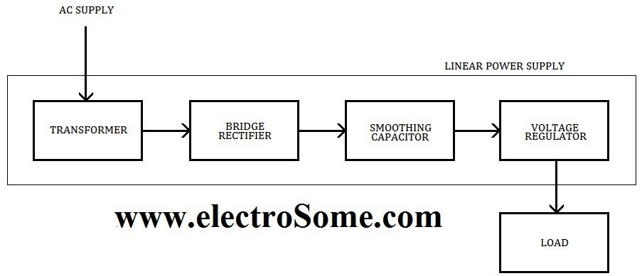
Here, we have got an input high voltage AC going into a transformer which usually steps down the high voltage AC from mains to low voltage AC required for our application. The following bridge rectifier and a smoothing capacitor to convert his AC voltage into unregulated DC voltage. But this voltage will change according to varying load and input stability. This unregulated DC voltage is fed into a voltage regulator which will keep a constant output voltage and suppresses unregulated voltage ripples. Now this voltage can be fed into our load.
Since the bridge rectifier has already been discussed in a previous page,I will not be going deeper into that section, so lets gets straight to the regulator circuit,
Simple Circuit Diagram
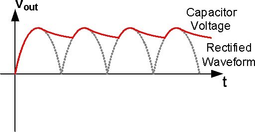
Firstly let us discuss about the need for the smoothing capacitance.As you know the out put of the bridge rectifier will be as follows

As you can see, although the waveform can be considered to be a DC voltage since the output polarity does not invert itself, the large ripples that exist inthe output makes sit almost impossible to be used in any powering applications.So it is to remove these ripples that the smoothing capacitor[C1] is used. Now the output after the capacitor will be
Now to design the capacitor we use the simple equation, Y=1/(4√3fRC)
where,
- Y = Ripple factor
- f = Frequency (here 50Hz)
- R = Required output voltage divided by maximum required output current
- C = Value of the capacitance to be used
To calculate Y we van use the equations,
Y=Vac-rms / Vdc
Vac-rms = Vr / 2√3
Vdc= VMax – (Vr / 2)
Now all we need to know is the value of Vr which can be selected according to our need. Normally we take it as 0.4V which means that the maximum size of ripples in the output waveform will be 0.4v. One dis advantage of this method is that the ripple factor depends in output current, ie. the ripples may become larger or smaller while we vary the load.This is the reason why it is absolutely necessary for the capacitor to be followed by a voltage regulator IC.
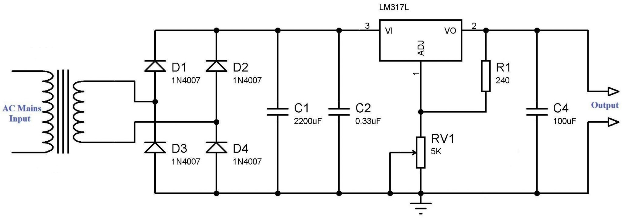
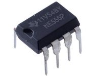
The most important part of this circuit is the 317 variable voltage regulator. The 317 is a monolithic integrated circuit with adjustable 3-terminal positive-voltage regulator designed to supply more than 1.5 A of load current with an output voltage adjustable over a 1.2 V to 37 V range. It also comes with internal current limiting, thermal shutdown, and safe area compensation.All this makes it a very good candidate for a regulator if we need a moderately accurate supply with medium power output. For more details you may refer it’s data sheet. As you can see it has three pins,
- INPUT – This is where we give the unregulated input
- OUTPUT – This is where we will get the regulated output
- ADJUST – The variable resistor connected to this pin, controls the output voltage
The design of the resistors are very simple, all we need to do is to follow the equations provided in the datasheet,
Vo = 1.25 x (1 + R2 / R1) + Iadj x R2
where,
- Vo = Output voltage
- R1,R2 = Resistor values
- Iadj = current through the ADJUST pin
Some important points to be noted are,
- ADJUST pin current must be about 50 to 100 uA. So we may neglect the second term of the equation to buy simplicity at the cost of accuracy.
- The value of R1 has to be kept fairly small some where upto 500 ohms. It is to satisfy the minimum voltage requirement of the IC.
So this leaves us with two more components in the circuit the needs our attention, capacitors C2 and C4. C2 is used to avoid ripples if filtering is performed at some distance from the regulator. Its valve is taken as 0.33 uF as prescribed in the datasheet. The capacitance C4 is very important in the circuit due to the fact that without this capacitance ,the 317 has a tendency to act as an oscillator in the Mhz ranges. It also has the added advantage of improving the transient response of the circuit.
Although these are the necessary components for the regulator to work properly, we advice adding some more elements to not only improve the efficiency of the circuit but also to provide added protection.the modified ciruit is given below,
Complete Circuit Diagram
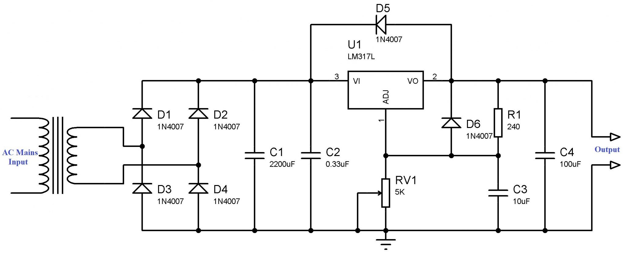
The capacitance C3 bypassing the ADJUST pin to ground will improve the ripple rejection capability while the diodes are used to protect the regulator from excess flowing through it if a battery or any other voltage source is connected across the output terminals of the regulator. Since the value of C1 is very large it will tend to act as a short circuit when such a condition exists. This will force a large current to flow through the regulator rendering it useless. By adding the diode D5 current will flow through the diode rather than the regulator and thus protecting it. The diode D6 does the same with capacitor C3 . The value of C3 can be taken as 10uF .
It is also clear from the data sheet that the worst case scenario dropout voltage for the LM317 is almost 2.3 V. So, to be in the safe side it is advisable to select a transformer with at least 4V greater than the required output voltage(2.3V of 317 + 1.4V of bridge rectifier).
Now we have a complete variable voltage regulator using LM317.
Don’t hesitate to post any doubts as the comments below.


Hi there!
Any reason why no to add additional capacitance to the output to filter and maybe make better sound with audio applications?
Thanks!
No.
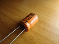
C1 needs to be an electrolytic capacitor, which has a high capacitance, here 2200 uF. Unfortunately such capacitors have a poor high frequency performance, so C2 is added – typically a ceramic capacitor, which has a very good high frequency performance. A much lower value, is needed – here 0.33 uF – more usually written as 330 nF.
Hello, please I wish to know if C1 and C2 can be merge to C, where C = C1+C2 ?
Thank you.
that is the voltage required by the Adjust terminal to create the equilibrium required by the regulator. So, whatever the choice of output voltage, in order to attain that, the Adjust terminal has to see 1.25VDC. You see, the voltage applied to the Adjust terminal is compared (by a comparator) to an internal preset 1.25 reference voltage. An error occurs whenever the two are not the same. The regulator will make adjustments to the output until the two are back into “equilibrium.”That is regulation and it is what makes these 3-terminal devices so simple to setup.
How to design 3-12V regulated variable dc power supply?
What is that 1.25 in Voutput equation?
i made center tapped arrangement using a center tapped transformer 10-0-15 i got 16 volts maximum as output from dc supply why i cannot get 24 volts?
and plz tell me why we are using two diodes with LM317T?
—===It is also clear from the data sheet that
the worst case scenario dropout voltage for the LM317 is almost 2.3 V.
So, to be in the safe side it is advisable to select a transformer
with at least 4V greater than the required output voltage(2.3V of 317 +
1.4V of bridge rectifier). ===—
If I select a transformer with an output voltage of 25 volts AC, the output from the diode bridge and get Capacitors C1 ~ 33 volts with no load. In this case, I can use the LM317T. And if a 36 volt AC outlet for the transformer, after the diode bridge and a capacitor C1, I get ~ 49 volts with no load. In this case, I can not use LM317T?
It is the ripple voltage. AC content in the output.
What is Vr in the formula ?
It will be Input Voltage – 1.5V
What is Vmax in formula??
Yes, it will.
It is just a filtering capacitor.
I have center tapped transformer output is 15-0-15 three wire can i use only 2 wire (15-0) it will work?
may i know wat is the purpose of connecting the c4 at the op terminal?
yes it will work
All capacitors that you have used are ceramic. Right ?
Hii. I am using a 12 volt fan at the output side. Which is supposed to rotate according to the variable output voltage. But at the same time I am using a 230:12 v transformer. Will it work ?
I made this. It worked just fine. Used 330ohm for R1 instead of 240.
Thank for advices
If you are interested in learning exactly how to generate power and reduce your bill then this is the perfect resource for you! With the ever increasing costs of living, there is no better time than right now to stop throwing money out the window and start generating our own electricity. Check w w w . i n p l i x . c o m and learn more about it.
Yes. electrolytic.. but 0.33 is ceramic..
Hello good day! I would like to inquire what capacitor you used? Is it electrolytic? I am still new in this. Thank you.
Hello… you are right..
I am extremely sorry for the inconvenience caused..
All errors are corrected..
Steve, you are correct. The diodes in the bridge are backwards in the schematic. We want conventional current to flow from the transformer to the “top end” of C1 and C2, so as to apply a positive filtered voltage to the input of the LM317. But, with the diodes as shown, positive conventional current flows to the “bottom end” of C1 and C2.
Use a resistor series with RV1 corresponding to 3V..
how can I make the circuit’s output to start from 3 v instead of 1.25 v?
hi, how did you arrive at the ripple factor, Vmax, Vac rms and Vdc in your circuit design?
It is same as bridge rectifier… . arrangement of diodes are different.. but it is correct..
Sorry, but as I understand it the arrow on a diode shows the direction of flow of conventional current. It seems to me therefore that your bridge rectifier is the wrong way around. Otherwise some good stuff thank you.