

Implementing XOR and XNOR Logic Functions using Diode Bridge and Transistor
Using DTL (Diode Transistor Logic) we can implement XOR and XNOR Logic Functions with a minimum number of Discrete Components.
 When we need to design Logic Circuits operating for higher than standard supply voltages, such as 30 and 24V, we can implement it by using regulators with standard logic family and interfacing it through Level Shifters. Alternatively we can implement Logic Gates from discrete electronic components and can be operated directly from the supply voltages if the Logic Circuits are not complex. We know that Basic Logic Functions AND, OR and NOT are straight forward and can be implemented easily but XOR and XNOR functions require combining of several Basic Logic Functions.
Here is an unusual method of performing exclusive functions using one Transistor, four Diodes, and 2 Resistors.
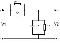
Circuit Diagrams:

First figure shows the Circuit Diagram of XNOR gate, it uses NPN transistor. When the voltage at A and B terminals are at opposite logic state, a voltage of higher voltage minus lower voltage minus 1.2V (voltage drop between two diodes) forward bias the Emitter-Base junction of the Transistor. This turns ON the transistor and the Logic LOW voltage available at the collector of the transistor is approximately equal to 0.6+VL+VCE, where VL is the Logic LOW input and VCE is the Collector to Emitter voltage of the transistor. When the both inputs A and B are at the same Logic Levels, the Emitter to Base junction of the transistor cannot be forward biased, thus the transistor is in OFF state and the output Y is at supply voltage.
The collector resistance 6.8K ohm is selected on the basis that to drive the A and B inputs with standard TTL (Transistor Transistor Logic) or CMOS and can be changed according to our application. Low Speed TTL is able to source 0.4mA and sink 8mA. The CMOS 4000 family is able to source and sink 1mA. A 0.4mA Logic HIGH current is sufficient for base current but a low at either A or B makes the Emitter current. It should be more concerned and should be limited to 1mA sink of the CMOS.
Second figure shows the circuit diagram of XOR gate, it uses PNP transistor. When the voltages at terminals A and B are at opposite logic states forward biases the Emitter-Base junction and turns ON the transistor. Thus an approximate Logic HIGH voltage VH−0.6V−VCE is available at output terminal Y. The Logic LOW voltage is approximately 0V but the sink current limited by the collector resistance 10K ohm.
As the Logic HIGH input current for TTL is approximately 0.4mA, which is the transistors emitter current and would generate a voltage drop of approximately 4V across 10K ohm resistor. But the problem is the 10K ohm resistor cannot provide the required sink current 0.4mA when the output Y is at Logic ZERO. Thus this XOR configuration seems to be suitable only for CMOS or TTL inputs at A and B and capable of driving only CMOS at output Y.
However, we can use previous XNOR configuration to make XOR by connection another inverting transistor after Y.


I think you should increase the base resistor 10K .. otherwise it may damage the transistor.
Hi, I would like to know if using figure 1(a), by applying either 82Vdc to A or B, would the circuit work? For the NPN transistor I would use TIP31C. The question is awkward, but is necessary for me in my design. Would really appreciate your help. The reason why it is 82Vdc is that I am testing a voltage suppression diode (bidirectional) which when 82Vdc passes through the diode, it will go directly into breakdown allowing to pass. When it reaches your figure 1(a), will it be allowed to work? Thanks.
So when you plan on using high voltages, God brings it to you/provides ample ground, and your design can just leave it out?
These are intended for applications with works with higher voltages than standard voltages.. like 24V or 30V..
Understand the working of the circuit first and then try to implement it.
It is an interesting idea but I’ve been unable to make them work.
Figure 1a doesn’t have any connection to GND.
Figure 1b has GND, but doesn’t connect to any supply voltage.
Have I missed something?