Controlling of DC Motors using MPU-6050
Contents
In this project, we are going to control the speed of 2 DC motors using the MPU-6050. MPU-6050 is an accelerometer and Gyro sensor. By moving the sensor in upward or downward direction, the speed of the motors will increase or decrease.
By moving the sensor in upward direction, the speed of first motor will increase and the speed of other motor will decrease. Similarly, by moving the sensor in downward direction, the speed of first motor will increase and the speed of other motor will decrease.
Components Required
The components required for this project are as follows
- Arduino Uno
- MPU-6050 (Accelerometer and Gyro sensor)
- L293D Motor Driver
- DC Motors
- 9V Battery
- Connecting wires
- Breadboard
Hardware
Circuit Diagram

Explanation
1) Firstly, we have to make the connections for L293D motor driver with Arduino. The connections of the L293D motor driver with the Arduino are as follows.
- Pin No. 1 of L293D IC is connected to 5V (Arduino 5V pin).
- Pin No. 2 of L293D IC is connected to Pin No. 6 of Arduino.
- Pin No. 3 of L293D IC is for the output of motor. Connect one end of the DC motor to Pin No. 3 of L293D and other end of the DC motor to Pin No. 6 of L293D.
- Pin No’s 4, 5, 12 and 13 are the ground pins; connect these to GND (Arduino GND pin).
- Pin No. 7 of L293D IC is connected to Pin No. 5 of Arduino.
- Pin No. 8 is the VCC pin, connect positive of battery to Pin No. 8 of L293D and the negative of battery to the Ground.
- Pin No. 9 of L293D IC is connected to 5V (Arduino 5V pin).
- Pin No. 10 of L293D IC is connected to Pin No.9 of Arduino.
- Pin No. 11 of L293D IC is the output pin for the second motor. Connect one end of motor to Pin No. 11 and the second end of motor to the Pin No. 14 of L293D.
- Pin No. 15 of L293D IC is connected to Pin No. 10 of Arduino.
- Pin No. 16 of L293D IC is connected to 5V (Arduino 5V pin).
2) Secondly, make the connections for MPU-6050 with the Arduino
- Connect VCC pin of MPU-6050 to the 5V pin of Arduino
- Connect GND pin of MPU-6050 to the GND of Arduino
- Connect SCL pin of MPU-6050 to the A5 of Arduino
- Connect SDA pin of MPU-6050 to the A4 of Arduino
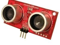
MPU-6050 Accelerometer + Gyro Sensor
The MPU-6050 is a 6 DOF (Degrees of Freedom) or a six-axis IMU sensor, which means that it gives six values as output. Three values from the accelerometer and three from the gyroscope. An accelerometer works on the principle of the piezoelectric effect and Gyroscopes work on the principle of Coriolis acceleration.
The MPU-6050 is a sensor based on MEMS (Micro Electro Mechanical Systems) technology. Both the accelerometer and the gyroscope are embedded inside a single chip. This chip uses I2C (Inter-Integrated Circuit) protocol for communication.
It is very accurate, as it contains 16-bits analog to digital conversion hardware for each channel. Therefor it captures the x, y, and z channel at the same time. The sensor uses the I2C-bus to interface with the Arduino.
Operation of MPU-6050
The structure of the accelerometer and gyro sensor has a mass attached to a spring which has fixed outer plates and moves along one direction. If an acceleration is applied in any of the direction, the capacitance between the plates and the mass will change. The accelerometer sensor will measure this change in capacitance which corresponds to an acceleration value.
Software
Arduino Uno Program
#include <Wire.h>
#include <MPU6050.h>

#define first_motor_pin1 5
#define first_motor_pin2 6
#define second_motor_pin1 9
#define second_motor_pin2 10

MPU6050 sensor;
int16_t ax, ay, az;
int16_t gx, gy, gz;

int first_motor_speed;
int second_motor_speed;

void setup ( )
{
  Wire.begin( );
  Serial.begin (9600);
  Serial.println ("Initializing the sensor");
  sensor.initialize ( );
  Serial.println(sensor.testConnection( ) ? "Successfully Connected" : "Connection failed");
  delay(1000);
  Serial.println("Taking Values from the sensor");
  delay(1000);
}

void loop ( )
{
  sensor.getMotion6(&ax, &ay, &az, &gx, &gy, &gz);
  ax = map(ax, -17000, 17000, -125, 125);
  first_motor_speed = 125+ax;
  second_motor_speed = 125-ax;

  Serial.print ("Motor1 Speed = ");
  Serial.print (first_motor_speed, DEC);
  Serial.print (" && ");
  Serial.print ("Motor2 Speed = ");
  Serial.println (second_motor_speed, DEC);

  analogWrite (first_motor_pin2, first_motor_speed);
  analogWrite (second_motor_pin2, second_motor_speed);
  delay (200);
}
Program Explanation
First of all, we included the library for the MPU-6050 sensor so that we can use MPU-6050 functions from the library. The MPU-6050 sensor works with Arduino through the SPI communication. Therefore, we have included the wire library which will enable the SPI communication.
#include <Wire.h>
#include <MPU6050.h>
Then we defined the pins where we have connected the motor wires. We connected the first motor to the pin no’s 5, 6 of Arduino and the second motor to the pin no’s 9, 10 of Arduino.
#define first_motor_pin1 5
#define first_motor_pin2 6
#define second_motor_pin1 9
#define second_motor_pin2 10
After that, we defined the variables which will help us in calculating the output.
MPU6050 sensor;
int16_t ax, ay, az;
int16_t gx, gy, gz;
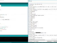
In the setup function, we checked that whether the sensor is working properly or not. If the sensor works properly, then it will print “Successfully Connected” otherwise it will print “Connection failed”.
Serial.println(sensor.testConnection( ) ? "Successfully Connected" : "Connection failed");
delay(1000);
Serial.println("Taking Values from the sensor");
Then we took the output from MPU-6050 sensor and mapped these from -125 to 125. Then we added and subtracted mapped value with 125.
sensor.getMotion6(&ax, &ay, &az, &gx, &gy, &gz);
ax = map(ax, -17000, 17000, -125, 125);
first_motor_speed = 125+ax;
second_motor_speed = 125-ax;
analogWrite (first_motor_pin2, first_motor_speed);
analogWrite (second_motor_pin2, second_motor_speed);
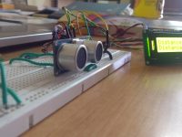
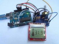
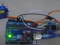
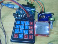
Practical Implementation

Working
Whenever we move the sensor in the upward or downward direction, the sensor gives the output from -17000 to 17000. The motors only require 0 to 255 pwm value to rotate. So, we will map these values from -125 to 125. Now, when we move the MPU-6050 towards upward direction, the output value which we will get is 125. Then will add 125 to this output value and this will be the speed of the first motor.
When we move the MPU-6050 towards downward direction, the output value which we will get is -125. We will subtract this from 125 and this will be speed for the second motor.