

Using Interrupt with PIC Microcontroller
Contents
Introduction
Interrupt is the one of the most powerful feature in embedded applications. Almost all the real time applications are implemented using Interrupts. So what is an Interrupt…??
As the name suggests Interrupts are special events that requires immediate attention, it stops a microcontroller/microprocessor from the running task and to serve a special task known as Interrupt Service Routine (ISR) or Interrupt Handler. Suppose you are at home, taking coffee. Suddenly your mobile phone rings. You stop taking coffee and answer the call. When you have finished the conversation, you will go back to take coffee. This process is similar to ISR execution. You can think the main service routine as taking coffee and the ringing of mobile phone is causes interrupt in taking coffee. This initiates your mobile phone conversation which is similar to executing ISR. When the mobile conversation is ended you will go back to the main service routine of taking coffee.
Need for Interrupts
Consider a MP3 player which build around microcontroller. It contains push button switches to select song, control volume etc. The microcontroller should be programmed to convert the data stored in MP3 files to electrical signal and to change controls according to the status of push button switches. Consider this application without using interrupt, the programmer wants to continuously do the following tasks.
- Read the status of push button switches and change controls accordingly.
- Read data from MP3 file.
- Convert it to electrical signal.
This processes of continuous monitoring is known as POLLING. This is not an efficient way of programming as it consumes all its processing time for monitoring. Consider if this problem is addressed using Interrupts. The microcontroller wants to respond only when an interrupt occurs.
Here is an analogy to understand the difference better. The method of polling is similar to a salesperson, who goes door-to-door to requesting to buy his product or service. This is similar to a microcontroller continuously monitoring the status of all devices attached to it. While the method of Interrupt is similar to a shopkeeper. Whoever needs his products or services goes to him and buy it. This is similar to microcontroller responds only when an interrupt occurs.
Hardware and Software Interrupts
PIC Microcontroller consists of both Hardware and Software Interrupts. If the interrupts are generated by external hardware at certain pins of microcontroller, or by inbuilt devices like timer, they are called Hardware Interrupts. While Software Interrupts are generated by a piece of code in the program. Also known as External and Internal Interrupts.
Interrupts in PIC 16F877A
PIC 16F877A has the following 15 interrupt sources :
- External
- Timer 0
- Timer 1
- RB Port Change
- Parallel Slave Port Read/Write
- A/D Converter
- USART Receive
- USART Transmit
- Synchronous Serial Port
- CCP1 (Capture, Compare, PWM)
- CCP2 (Capture, Compare, PWM)
- TMR2 to PR2 Match
- Comparator
- EEPROM Write Operation
- Bus Collision
The 5 registers that used to control the operation of Interrupts in PIC 16F877A Microcontroller :
- INTCON
- PIE1
- PIR1
- PIE2
- PIR2
This article deals with external interrupt. INTCON register is used to configure External Interrupts.
INTCON Register

INTCON Register is a readable and writeable register which contains various enable and flag bits for External and Internal Interrupts.
GIE – Global Interrupt Enable
1 – Enables all unmasked interrupts
0 – Disables all interrupts
PEIE – Peripheral Interrupt Enable
1 – Enables all unmasked peripheral interrupts
0 – Disables all peripheral interrupts
TMR0IE – Timer 0 Overflow Interrupt Enable
1 – Enables the TMR0 interrupt
0 – Disables the TMR0 interrupt
INTE – RB0/INT External Interrupt Enable
1 – Enables the RB0/INT external interrupt
0 – Disables the RB0/INT external interrupt
RBIE – RB Port Change Interrupt Enable
1 – Enables the RB port change interrupt
0 – Disables the RB port change interrupt
TMR0IF – Timer 0 Overflow Interrupt Flag
1 – TMR0 register has overflowed. It must be cleared in software.
0 – TMR0 register did not overflow
INTF – RB0/INT External Interrupt Flag
1 – The RB0/INT external interrupt occurred. It must be cleared in software.
0 – The RB0/INT external interrupt did not occur
RBIF – RB Port Change Interrupt Flag
1 – At least one of the RB7 – RB4 pins changed state, a mismatch condition will continue to set
the bit. Reading PORTB will end the mismatch condition and allow the bit to be cleared. It must be cleared in software.
0 – None of the RB7 – RB4 pins have changed state
INTEDG bit of OPTION_REG Register is the Interrupt Edge Select bit. When it is 1 interrupt is on rising edge of RB0/INT pin and when it is 0 interrupt is on falling edge of RB0/INT pin.
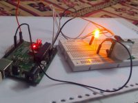
Circuit Diagram

Note: VDD and VSS of the pic microcontroller is not shown in the circuit diagram. VDD should be connected to +5V and VSS to GND.
Working
A push button switch is connected to the External Interrupt pin INT of the PIC Microcontroller. When this button is pressed, the microcontroller is interrupted and the ISR is executed. The ISR toggles the status of PORTC for 1 second.
MikroC Code
Interrupts can be easily handled by using reserved word ‘interrupt’. MikroC PRO for PIC Microcontrollers implicitly declares a function ‘interrupt’ to handle interrupts which cannot be redeclared.
void main()
{
  TRISC = 0; // To configure PORTC as output port
  OPTION_REG.INTEDG = 1; // Set Rising Edge Trigger for INT
  INTCON.GIE = 1; // Enable The Global Interrupt
  INTCON.INTE = 1; // Enable INT
  while(1)
  {
    PORTC = 0x00; //Set some value at PortD
  }
}

void interrupt() //  ISR
{
 INTCON.INTF=0; // Clear the interrupt 0 flag
 PORTC=~PORTC; // Invert (Toggle) the value at PortD
 Delay_ms(1000); // Delay for 1 sec
}
Download Here
You can download the hex file, MikroC source code, Proteus files etc here…


hi sir,
i need a cod for pic16f877a that receive a range of analog signal, convert to digital and display on the screen, and lastly send an sms to a phone number if the value exceed 100.
thanks
Been tearing my hair out. So thankful for this post.
#include
__CONFIG(0x3d72);//nsk pic board used this command
void timer() //timer function
{
for(int i=0;i<200;i++) //1 sec calculation loop
{
TMR0 = 0x9E;
while (TMR0IF == 0); //timer flag
TMR0IF=0;
}
}
void main(void)
{
TRISD = 0x00;
PORTD = 0x00;
//timer
T0CS =0;
PSA =0;
PS2 =1;
PS1 =1;
PS0 =1;
//interrupts
GIE=1; //global interrupt enable
INTF=0; //clear interrupt flag bit
INTEDG=1; //configure detection of interrupt on rising edge
while(1)
{
RD0=1;
if (INTF==1)
{
RD1 = 1;
timer();
RD1 = 0;
timer();
INTF=0;
}
timer() ;
RD0 = 0;
timer() ;
}
}
Ligo George Mod PICMICRO • 3 years ago
Try doing like this :
unsigned int cnt;
void main()
{
cnt = 0;
…
…
}
void interrupt()
{
…
..
cnt++;
…
}
I did this, but my count is getting incremented by 2.
hi , i am an electronic engineering student , and i was trying to learn how we can use interrupts , while that period i tried a code , but unfortunately effort unsucceed and by searching through the internet could to find your code, and i copied down it and applied for my proteus simulation also , the same result could to see , interrupt doesn’t response…This is the code which i am trying to success on proteus simulation.
void main() {
TRISD=0b11110000; //TRISD AS OUTPUT
TRISB=0b00000011; //TRISB AS INPUT
//OPTION_REG.F7=0;//ENABLE PULLUPS
INTCON.GIE=1; //bit7 of INTCON ENABLE
INTCON.INTE=1; //BIT4 OF INTCON ENABLE (RBO)
OPTION_REG.INTEDG=1; // BIT6 OF OPTION REGISTER ENABLE
//OPTION_REG=0b00111111;
//INTCON=0b10010000;
while(1){
if(PORTB.F1==1){
PORTD.F0=1;
Delay_ms(100);
PORTD.F0=0;
Delay_ms(100);
PORTD.F1=1;
Delay_ms(100);
PORTD.F1=0;
Delay_ms(100);
PORTD.F2=1;
Delay_ms(100);
PORTD.F2=0;
Delay_ms(100);
PORTD.F3=1;
Delay_ms(100);
PORTD.F3=0;
Delay_ms(100);
PORTD.F2=1;
Delay_ms(100);
PORTD.F2=0;
Delay_ms(100);
PORTD.F1=1;
Delay_ms(100);
PORTD.F1=0;
Delay_ms(100);
PORTD.F0=1;
Delay_ms(100);
PORTD.F0=0;
Delay_ms(100);
}
else {
PORTD=0b00000000;
}
}
}
void interrupt(){ //ISR
INTCON.INTF=0;//CLEAR INTERRUPT FLAG
PORTD=0b00000000;
Delay_ms(1000);
}
PORTB on change interrupt is used in the following project :
https://electrosome.com/hc-sr04-ultrasonic-sensor-pic/
how to use PORTB Change Interrupts in the controller
It is already explained in the article.
The interrupt will be triggered during rising edge (LOW to HIGH transition) of RB0/INT interrupt pin..
Hi, i’m new to PIC programming. Can’t find a clue to what this line is for in the article! Can you explain it?
“OPTION_REG.INTEDG = 1; // Set Rising Edge Trigger for INT”
I will try to post a tutorial.
can u explain for pic18f452 and how i can choose one of three interrupt?
Hi, I know that, furtunately found the problem. 16F887 needs to clear ANSELH.
Anyway thankx for the project, I learned a lot.
Hello, the above program is for PIC 16F877A not for 16F877
For that you should enable UART Interrupt.. Check Interrupt Registers.
Hi,I have tried to rebuild your project but did not succeded.
Here is my code but doesnot work and I dont know why, any glue?
(PIC16F887, 4MHz, the diargam is the same.)
void interrupt(){
// if (INTCON.RBIF==1) { // RB interrupt jött
PORTD.F7 = ~PORTd.F7 ;
INTCON.INTF = 0; // Clear the interrupt 0 flag
delay_ms(1000);
// INTCON.RBIF = 0; // RB interrupt jelző törlés
// }
}
////////////////////////////////////////////////////////////////
void main() {
TRISA = 0; // PORTA is digital, not analog
TRISB = 0b1; // PORTB R0 és R1 INPUT
TRISC = 0; // PORTC is Output
TRISD = 0; // PORTD is output
// WPUB = 0; // WEAK PULL UP 1 enabled
INTCON.GIE = 1; //Enable global interrupt function – FŐ engedély
INTCON.INTE = 1; //Enable RB0/INT externalnterrupt
// INTCON.PEIE = 1; //Enable all unmasked peripheral interrupt
// INTCON.RBIE = 1; //ENable RB int
OPTION_REG.INTEDG = 1; //Interrupt on rising edge
// IOCB = 0b11; // enable rb0 rb1 interrupt
do {
PORTc.F7 = ~PORTc.F7 ;
delay_ms(1000);
} while (1);
}
Hi how can i use interrupt in the uart receiving to programme a circular buffer
thx a lot for reply
Try doing like this :
unsigned int cnt;
void main()
{
cnt = 0;
…
…
}
void interrupt()
{
…
..
cnt++;
…
}
Hi,George
How can i count number of interrupt received by the PIC for a specific time?for example if i want to count the rising edge number for the period of 30sec.what will be code?
You can connect push button to any pin of microcontroller which is configured as input pin…
You can check the status of that pin through the program…
Read the following article :
http://electrosome.com/push-button-switch-pic-microcontroller/
So, How we can manage button events?
Interrupt is not intended to connect push button switches… It is used above to demonstrate the working of interrupt..
Will be published in future..
How to add more push buttons?
HTC code?
please provide some examples in htc, microc ..
I like the way you explained it
Thanx man. This helps a lot!!!