

Interfacing LCD with PIC Microcontroller – CCS C
Contents
In this tutorial we will see How to interface a 16×2 character LCD Module with PIC 16F877A Microcontroller using CCS C Compiler. 16×2 character LCD is a very commonly used LCD module in electronic projects and products. 16×2 means it can display 2 rows of 16 characters. It is a very basic and low cost module. Its other variants such as 16×1, 20×4 are available in the market. In these displays each character is displayed using 5×8 or 5×10 dot matrix. These LCDs commonly uses HD44780 compliant controllers for their operation.

Interface between a microcontroller and LCD can be 4-bit or 8-bit. The difference between 4-bit and 8-bit is how data are send to the LCD. To write an 8-bit character to the LCD module in 8-bit mode, ASCII data is send through the data lines DB0- DB7 and data strobe is given through the E line.
But 4-bit mode uses only 4 data lines. In this mode the 8-bit ASCII data is divided into 2 parts which are send sequentially through data lines DB4 – DB7 with its own data strobe through the E line. The idea of 4-bit communication is to save as much pins that used to interface with LCD. The 4-bit communication is a bit slower when compared to 8-bit. The speed difference is only minimal, as LCDs are slow speed devices the tiny speed difference between these two modes is not significant. Remember that our microcontrollers works in the speed of MHz range. Thus the 4-bit mode data transmission is most commonly used.
CCS C provides a built in library file, “lcd.c” for interfacing LCDs having HD44780 compliant controllers using 4-bit mode communication. Just include this file in your program and enjoy.
CCS C LCD Library
LCD Connections
For the proper functioning of LCD Library, you should define the connections of below 7 pins used for LCD interfacing in the program.
- Enable – E or EN
- Register Select – RS
- Read / Write – RW
- Data 4 – DB4 or D4
- Data 5 – DB5 or D5
- Data 6 – DB6 or D6
- Data 7 – DB7 or D7
These must be defined before including the header file, it can be done in two ways as given below.
PORT Access Method
This method requires the entire 7 bit interface connected to same GPIO port. It should be defined before including the header file as shown below.
#define LCD_DATA_PORT getenv("SFR:PORTD")
This defines that the entire 7 bit interface is connected to PORTD of PIC Microcontroller.
PIN Access Method
In this method you can connect those 7 bits to any GPIO pins and it should be defined before including the header file as shown below.
//LCD Module Connections
#define LCD_RS_PIN PIN_D1
#define LCD_RW_PIN PIN_D2
#define LCD_ENABLE_PIN PIN_D3
#define LCD_DATA4 PIN_D4
#define LCD_DATA5 PIN_D5
#define LCD_DATA6 PIN_D6
#define LCD_DATA7 PIN_D7
//End LCD Module Connections
Important Functions
lcd_init()
This function must be called before any other lcd functions. It initializes the LCD module with above defined connections.
lcd_putc(c)
This function will display c on the next cursor position of the LCD. You can print strings and characters using this function. You can also use following backslash character constants for sending different commands to LCD.
- \\a – To set cursor to the upper left
- \\f – To clear display and set cursor to upper left
- \\n – To go to start of next line
- \\b – To move back one position
lcd_gotoxy(x, y)
This function can be used to set cursor position of the LCD, upper left position is (1,1).
lcd_getc(x, y)
This function returns the character at the position (x, y) on the LCD.
lcd_cursor_on(int1 on)
This function can be used to turn the cursor on or off.
Example :
lcd_cursor_on(TRUE); //Turns ON the cursor
lcd_cursor_on(FALSE); //Turns OFF the cursor
Note : For more details you can read the library file “lcd.c” in the location C:/Program Files/PICC/Drivers/.
Usage of printf()
printf() can output a string of characters to standard UART pins or to a specified function. It can be used with CCS C LCD library to format output strings. By thus we can print integers, floating point numbers etc using this.
Syntax :
printf(fname, cstring, values...);
Where,
- fname is the function name, here we can use lcd_putc.
- string is a constant string or a null terminated array of characters. Formatting is done in accordance with this argument.
- values is a list of variables separated by commas.
Format
The generic form of format is %nt. where n is optional which may be 1 – 9 to specify number of characters to be outputted or 01 – 09 to indicate leading zeros or 1.1 to 9.9 for floating point and %w formats. t is the type which may be one of the following.
| t | Type |
|---|---|
| c | Character |
| s | Sting or Character |
| u | Unsigned Integer |
| d | Signed Integer |
| Lu | Long Unsigned Integer |
| Ld | Long Signed Integer |
| x | Hex Integer – lower case |
| X | Hex Integer – upper case |
| Lx | Hex Long Integer – lower case |
| LX | Hex Long Integer – upper case |
| f | Float with truncated decimal |
| g | Float with rounded decimal |
| e | Float in exponential format |
| w | Unsigned Integer with decimal place inserted. Specify two numbers for n. The first is a total field width. The second is the desired number of decimal places. |
Example :
To print an integer :
printf(lcd_putc,"Count = %d", i);
When i = 0, output will be : Count = 0
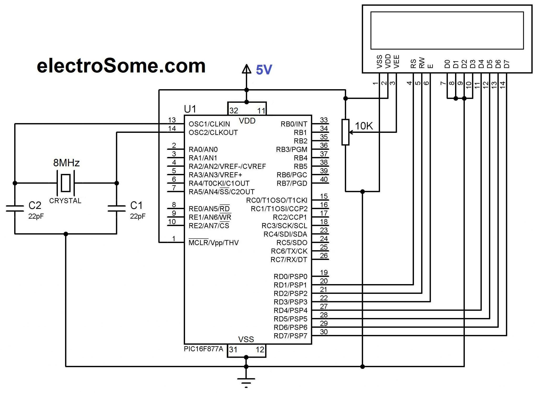
Circuit Diagram
CSS C Code
//LCD Module Connections
#define LCD_RS_PIN PIN_D1
#define LCD_RW_PIN PIN_D2
#define LCD_ENABLE_PIN PIN_D3
#define LCD_DATA4 PIN_D4
#define LCD_DATA5 PIN_D5
#define LCD_DATA6 PIN_D6
#define LCD_DATA7 PIN_D7
//End LCD Module Connections

#include <main.h>
#include <lcd.c>

#use delay (clock=8000000)

void main()
{
  int i=0;

  lcd_init();
  Delay_ms(100);

  while(TRUE)
  {
    lcd_putc('\\f');                   //Clear Display
    lcd_putc("Hello World");
    Delay_ms(2000);
    lcd_putc('\\f');                   //Clear Display
    lcd_putc("Welcome To");
    lcd_gotoxy(1,2);
    lcd_putc("LCD Library");
    Delay_ms(2000);
    lcd_putc('\\f');                   //Clear Display
    printf(lcd_putc,"Count = %d", i); //Display Count
    Delay_ms(2000);
    i++;
  }
}
Downlaod
You can download CCS C files and Proteus files here.


To anyone still reading, check that Proteus is in “Debug” mode (drop-down list from the toolbar), to prevent the .hex file from changing. If Proteus is in release, it tells CCS C to update the .hex file, because its expecting an upload to hardware. Also right click the PIC in Schematic Capture, and check its properties. It should be running off of the same firmware as your choice in the drop-down menu (i.e. Debug.cof or Release.hex) .
same problem bro 🙁
Hi,
Make sure that the device type, frequency and other settings are correct.
Good morning sir,
Thank you enormously for this work, which requires an intellectual effort and time.
I’m newbie, I have a problem and I want to ask you a question:
I install “CCS compile” it works very well and I install “Proteus 7 profetionnal” and I download “Interfacing with PIC Microcontroller LCD – CCS C”, as it works very well.
The problem is that when I open the file “main.c” and I do “compile” without changing any program instruction, the file “main.hex” changed and is not working.
I could not locate the problem, please help me.