

Interfacing LCD with PIC Microcontroller – MPLAB XC8
Contents
In this tutorial we will see How to Interface a 16×2 character LCD module with PIC 16F877A Microcontroller using MPLAB X IDE and MPLAB XC8 C Compiler. 16×2 Character LCD is a very basic and low cost LCD module which is commonly used in electronic products and projects. 16×2 means it contains 2 rows that can display 16 characters. Its other variants such as 16×1 and 16×4 are also available in the market. In these displays, each character is displayed using 5×8 or 5×10 dot matrix.
For controlling LCD using MPLAB XC8 compiler we need to know the hardware of LCD. These LCDs commonly uses HD44780 compliant controllers. So we need to learn HD44780 Dot Matrix LCD Controller Datasheet. Don’t worry we already developed an LCD library including commonly used functions, so you can use it without any hardware knowledge of LCD.

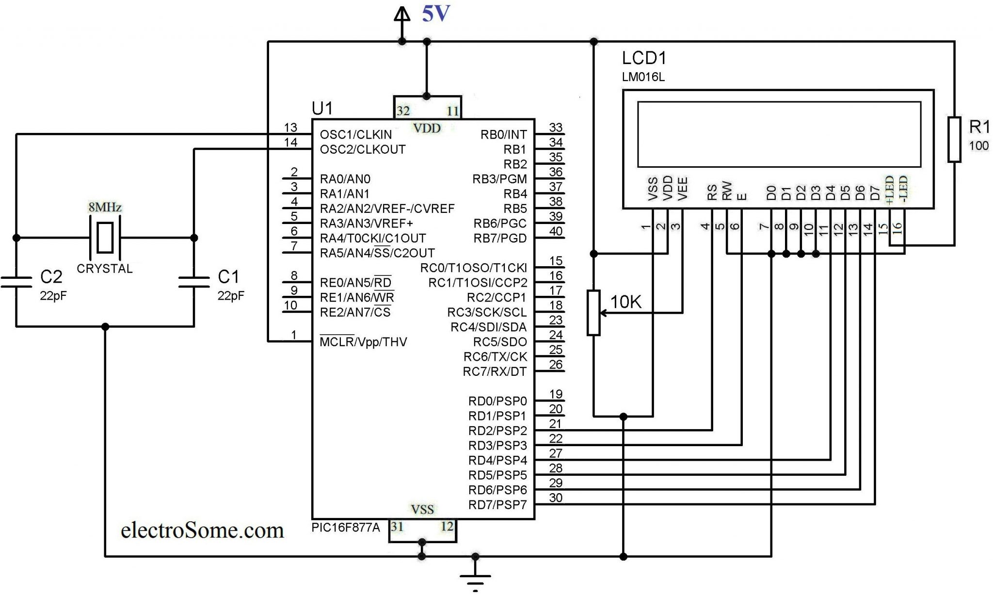
First two pins GND and VCC (VSS and VDD) are for providing power to LCD display. 3ed pin VEE is used to control the contrast of the LCD display. A 10KΩ preset whose fixed ends connected to VDD, VSS and variable end connected to VEE can be used to control contrast of the LCD. A microcontroller or microprocessor need to send 2 types of information for operating this LCD Module, Data Information and Command Information. Data Information is the ASCII value of the characters to be displayed in the LCD screen and Command Information determines other operations such as position to be displayed, clear screen, shift etc. Data and Command Information are send to LCD through same data lines (DB0 – DB7) which are multiplexed using RS (Register Select) pin of LCD. When RS is HIGH LCD treats DB0 – DB7 data pins information as Data to be displayed and when it is LOW LCD treats it as Command Information. Enable (E) input of the LCD is used to give Data Strobe. HIGH (5V) Voltage Level in the Enable (E) pin tells the LCD that DB0 – DB7 contains valid information. The input signal R/W (Read or Write) determines whether data is written to or read from the LCD. In normal cases we need only writing hence it is tied to GROUND in circuit shown below.
The interface between this LCD and Microcontroller can be 8 bit or 4 bit and the difference between them is in how the data or commands are send to LCD. In the 8 bit mode, 8 bit data and commands are send through the data lines DB0 – DB7 and data strobe is given through E input of the LCD. But 4 bit mode uses only 4 data lines. In this 8 bit data and commands are splitted into 2 parts (4 bits each) and are sent sequentially through data lines DB4 – DB7 with its own data strobe through E input. The idea of 4 bit communication is introduced to save pins of a microcontroller. You may think that 4 bit mode will be slower than 8 bit. But the speed difference is only minimal. As LCDs are slow speed devices, the tiny speed difference between these modes is not significant. Just remember that microcontroller is operating at high speed in the range of MHz and we are viewing LCD with our eyes. Due to Persistence of Vision of our eyes we will not even feel the speed difference.
Hope that you got rough idea about how this LCD Module works. Actually you need to read the datasheet of HD44780 LCD driver used in this LCD Module to write a MPLAB XC8 program for PIC. But we solved this problem by creating a header file lcd.h which includes all the commonly used functions using 4 bit mode. Just include it and enjoy.
Circuit Diagram
LCD Library
- Lcd_Init() : This function will initialize the LCD Module connected to the following defined pins.
#define RS RD2
#define EN RD3
#define D4 RD4
#define D5 RD5
#define D6 RD6
#define D7 RD7
These connections must be defined for the proper working of LCD.
- Lcd_Clear() : To clear the display.
- Lcd_Set_Cursor(int row, int column) : This function is used to set row and column of the cursor on the LCD screen. By using this function we can change the position of the character or string displayed by following functions.
- Lcd_Write_Char(char) : To write a character to LCD on the current position.
- Lcd_Write_String(char *string) : To write string to LCD on the current position.
- Lcd_Shift_Right() : To shift contents on the LCD screen Right once without changing the data in the Display RAM.
- Lcd_Shift_Left() : To shift contents on the LCD screen Left once without changing the data in the Display RAM.
Note : The Pins to which LCD is connecting should be configured as Output Pins by writing to TRIS Register.
MPLAB XC8 Code
#define _XTAL_FREQ 8000000

#define RS RD2
#define EN RD3
#define D4 RD4
#define D5 RD5
#define D6 RD6
#define D7 RD7

#include <xc.h>
#include "lcd.h";

// BEGIN CONFIG
#pragma config FOSC = HS // Oscillator Selection bits (HS oscillator)
#pragma config WDTE = OFF // Watchdog Timer Enable bit (WDT enabled)
#pragma config PWRTE = OFF // Power-up Timer Enable bit (PWRT disabled)
#pragma config BOREN = ON // Brown-out Reset Enable bit (BOR enabled)
#pragma config LVP = OFF // Low-Voltage (Single-Supply) In-Circuit Serial Programming Enable bit (RB3 is digital I/O, HV on MCLR must be used for programming)
#pragma config CPD = OFF // Data EEPROM Memory Code Protection bit (Data EEPROM code protection off)
#pragma config WRT = OFF // Flash Program Memory Write Enable bits (Write protection off; all program memory may be written to by EECON control)
#pragma config CP = OFF // Flash Program Memory Code Protection bit (Code protection off)
//END CONFIG

int main()
{
    unsigned int a;
    TRISD = 0x00;
    Lcd_Init();
    while(1)
    {
        Lcd_Clear();
        Lcd_Set_Cursor(1,1);
        Lcd_Write_String("LCD Library for");
        Lcd_Set_Cursor(2,1);
        Lcd_Write_String("MPLAB XC8");
        __delay_ms(2000);
        Lcd_Clear();
        Lcd_Set_Cursor(1,1);
        Lcd_Write_String("Developed By");
        Lcd_Set_Cursor(2,1);
        Lcd_Write_String("electroSome");
        __delay_ms(2000);
        Lcd_Clear();
        Lcd_Set_Cursor(1,1);
        Lcd_Write_String("www.electroSome.com");

        for(a=0;a<15;a++)
        {
            __delay_ms(300);
            Lcd_Shift_Left();
        }

        for(a=0;a<15;a++)
        {
            __delay_ms(300);
            Lcd_Shift_Right();
        }

        Lcd_Clear();
        Lcd_Set_Cursor(2,1);
        Lcd_Write_Char('e');
        Lcd_Write_Char('S');
        __delay_ms(2000);
    }
    return 0;
}
sprintf() to Format Outputs
sprintf() can be used to write formatted string to a variable. It can be used with this LCD library to format displayed texts. This enables us to display integers and floating point numbers on the LCD very easily. You should include the header file stdio.h for using sprintf().
Syntax :
sprintf(char * str, const char * format, ...);
Where,
- str is the pointer to the buffer to which the resulting string is to be stored.
- format is a constant string or null terminated array of characters. Formatting is done in accordance with this argument.
- … (additional arguments) indicate a list of additional arguments that may required for this function depending up on the format string. Each additional argument contains a value that to be replace a format specifier in the format string.
Format Specifiers
The generic form of format is %nt. where n is optional which may be 1 – 9 to specify number of characters to be outputted or 01 – 09 to indicate leading zeros or 1.1 to 9.9 for floating point and %w formats. t is the type which may be one of the following.
| t | Type |
|---|---|
| c | Character |
| s | Sting or Character |
| u | Unsigned Integer |
| d | Signed Integer |
| Lu | Long Unsigned Integer |
| Ld | Long Signed Integer |
| x | Hex Integer – lower case |
| X | Hex Integer – upper case |
| Lx | Hex Long Integer – lower case |
| LX | Hex Long Integer – upper case |
| f | Float with truncated decimal |
| g | Float with rounded decimal |
| e | Float in exponential format |
| w | Unsigned Integer with decimal place inserted. Specify two numbers for n. The first is a total field width. The second is the desired number of decimal places. |
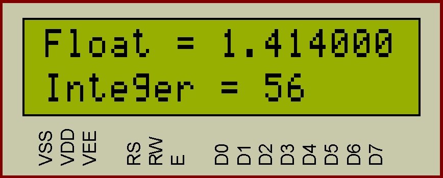
Example :
....
float f = 1.414;
int a = 56;
char s[20];
....
....
sprintf(s, "Float = %f", f);
Lcd_Set_Cursor(1,1);
Lcd_Write_String(s);
sprintf(s, "Integer = %d", a);
Lcd_Set_Cursor(2,1);
Lcd_Write_String(s);
This code will make following output on the LCD.
Please go to this page for more details about formatting.
Download Here
If you have and doubts, just comment below. You can download the entire project files here…


You should include the header file stdio.h to use sprintf(). By the way thanks for asking this question, I have included this information in the article also.
Hi. I cannot use the sprintf function. I get an error in building the code. How should be included, the sprintf function?
You can download it above, in the downloads section.
https://electrosome.com/lcd-pic-mplab-xc8/#Download_Here
how do add lcd.h header file in the project
I am not sure about this particular LCD. But you can use any LCD which uses a controller compatible with HD44780. So first check whether this LCD controller is HD44780 compatible. If not you might need to make minor changes as per the specifications of that particular controller. In my experience, most of these kinds of LCD’s controller are compatible to HD44780.
Hello, Ive ordered the pic you re using, but my lcd is a qapass 16×2 lcd ( from the elegoo mega 2560 kit). From your experience, do you know if the lcd controller is compatible or do i need to buy a new lcd…where did you buy yours from? Does it exist on amazon or ebay? If yes could you provide a link?
Thank you!!!
please why i can’t display lcd and how i can fix lcd.h https://uploads.disquscdn.com/images/aa229a7c89830683dec684bf7d9886e3c576bc400642bc50e6e01440b7cc44bc.png
I need this
Thanks . your code works for pic16f877a. I have a problem that i want lcd display output using pic16f1509. I did simulation in proteus using pic16f1509. I got proper lcd display output in simulation but practically i’m getting blinking of boxes in lcd display. Please suggests me , what are the changes have to be done ?
I have warning, MPLAB V5 XC8, PIC18F4550, Internal oscillator,
but it works great, It’s a great help !!!
warning is
./lcd.h:7:3: warning: ‘RD4’ is deprecated [-Wdeprecated-declarations]
D4 = 1;
^
main.c:5:12: note: expanded from macro ‘D4’
#define D4 RD4
^
hello . We need some help and ı was hoping you can help us.
We have one school project about servo motor and we had some research but we couldnt find anything yet. we study electrical-electronic engineer so it is not so easy for us. We used matlab, arduino , labview , autocad. And now it is diffrent program for project. And we are not professional on mplab .
My project make servo motor with mlabx -xc8 and we will use keypad and LCD. Also we will use PIC16f877a . İt taked so much days and our final week came. So ı losted. I hope you can help us. Thank you . And best regards.
Did you tried other programs ? It is not an error of above program. Try changing the microcontroller or programmer.
Link is already provided in the above article.
Hey where can i get LCD.h and UART.h files
it misses the file lcd.c so that it works, it is not in the zip fil
HI SIR. If i use pic18f248 processor, what modifications need to be done? i am using 16 mhz oscillator with a hardwear device
Thanks
Yeah great post … Can i get the code for LCD interface ? thanks in advance (mail id – [email protected])
Thanks for the tutorial. I am new to programming pic microcontrollers and I have a problem. I am trying to program a PIC16F877A to run a nokia 5110 display. In the codes you provided, lcd.h library is used. However it seems like I do not have it in my MPLABX v4.05. Do you have link to download the library?
HI, Who i can print pixel whit the LCD, creating news caracters, example pacman or gasper
This code is ok with a PIC16F1619 microcontroller ?
Programming Target (4/28/2017 12:54:35 PM)
PIC16F877A found (Rev 0x8)
Erasing Target
Programming Configuration Memory
Verifying Configuration Memory
PK2Error0027: Failed verify (Address = 0x2007 – Expected Value 0x2F4A – Value Read 0xA85)
PICkit 2 Ready
We have encountered this problem when the code is programmed. What can I get rid of this problem?
Hi Ligo, I need your help.. your code is working fine.. I want to add underline cursor or blinking cursor.. can you suggest some way for this? I tired but i am facing some issues.
Hi, Ligo can you provide xc8 code for 16×1 LCD interfacing with PIC?? Thanks in advance.
Check the datasheet of your LCD controller, you might need to make some changes depending on it.
Hi, I need to show 4 messages in differents lines , I have intented with “LM044L” LCD, but until now I have been unable. Thanks
It means that you need to reduce the delay. Just split it in to two delays and try.
That is not a problem. For simulating LED is not required. It will work fine in simualtion without those LED connections.
This code won’t work in dsPIC. You need to make a lot of changes for that.
In the proteus circuit, the LCD LM016L does not have the last two ports LED+ and LED-
i have loaded ur code to the pic16F877A and did all the connections the way u did except for those two LED ports in the lcd, and the lcd didn’t show anything when i ran it, any help?
First, thanks a lot, this tutorial and the one for interfacing the HC-SR04 are awesome!!
So I am having issues trying to get the code to compile. I am using the dsPIC33f with XC16 compiler to attempt to build this. I have changed all of the RDs to RBs, as my chip doesn’t have port D available. I am running into the issue within the lcd.h file and it is giving me the error that ” ‘RB4’ undeclared (first use in this function)” for pretty much all of the RB pins. Also, within the main.c I am getting errors for all of the pragma config statements “unknown configuration setting: ‘FOSC'” etc. Any help you might be able to give would be much appreciated. Thanks!
You need to include the header file stdio.h for that.
Hi, As I can see if you are using Internal Clock you also need to set OSCCON in your main program e.g. OSCCON = 0x071; This will set the internal clock to 8Mhz
Hi Ligo, Yes the header file is included and the main program is working great. The problem is only with the ‘sprintf’ example – I copied the code exactly as given but the program is returning ‘ build failed’. There are some empty spaces (dots) in your example, what does this mean. Appreciate your help. Thanks
did you include the header file ?? and make sure that your sprintf syntax is correct.
Yes, contrast and backlight are different.
Hi, I am a rather late entrant to this world. Your LCD program works great! However have problems when using the sprint method to display the examples you shared viz., the Float and Integer. MPLAB X IDE returns “…..error 1098 conflicting declarations for variable “_sprintf”. Also “Build failed”. Your inputs will be of great help. I can share the code sample if required. Thanks
I haave checked the connections and they seem fine. Would i need to worry about contrast if the backlight is not used ? I still have no luck !:(
Yes i believe they are also would i need to check contrast if backlight is not connected?
Hi,
Make sure that all connections are correct and also try adjusting the contrast.
Hi
How may I run two hour meter with same speed.?
I tried but I am getting 1 sec delay in each increments.
Hour1-0000
Hour2-0001
while I want
Hour1-0000
Hour2-0000
Hence I want that both hourmeter should run with incremental rate.
Please please please!! can some one help I cannot get it to work.
I only get the top row showing blocks as if I am only applying power.
I am using the pic16f690.
I have made the following changes and connections
#define RS RC0
#define EN RC1
#define D4 RC2
#define D5 RC3
#define D6 RC4
#define D7 RC5
also I have TRISC 0x00
I am using the internal clock and as far as I know I have emended the code accordingly
lcd.h
#include
//LCD Header for 4 bit Data -MPLABX/XC8
#define _XTAL_FREQ 8000000
#define RS RC0
#define EN RC1
#define D4 RC2
#define D5 RC3
#define D6 RC4
#define D7 RC5
char temp,z,y;
int i;
void Lcd_Port(char a)
{
if(a & 1)
D4 = 1;
else
D4 = 0;
if(a & 2)
D5 = 1;
else
D5 = 0;
if(a & 4)
D6 = 1;
else
D6 = 0;
if(a & 8)
D7 = 1;
else
D7 = 0;
}
void Lcd_Cmd(char a)
{
RS = 0; // D0 to D7 interpreted as Command
Lcd_Port(a);
EN = 1; // LCD Enable
__delay_ms(4);
EN = 0; // LCD Disable
}
Lcd_Clear()
{
Lcd_Cmd(0);
Lcd_Cmd(1);
}
void Lcd_Set_Cursor(char a, char b)
{
char temp,z,y;
if(a == 1)
{
temp = 0x80 + b – 1;
z = temp>>4;
y = temp & 0x0F;
Lcd_Cmd(z);
Lcd_Cmd(y);
}
else if(a == 2)
{
temp = 0xC0 + b – 1;
z = temp>>4;
y = temp & 0x0F;
Lcd_Cmd(z);
Lcd_Cmd(y);
}
}
void Lcd_Init()
{
Lcd_Port(0x00);
__delay_ms(20);
Lcd_Cmd(0x03);
__delay_ms(5);
Lcd_Cmd(0x03);
__delay_ms(11);
Lcd_Cmd(0x03);
Lcd_Cmd(0x02);
Lcd_Cmd(0x02);
Lcd_Cmd(0x08);
Lcd_Cmd(0x00);
Lcd_Cmd(0x0C);
Lcd_Cmd(0x00);
Lcd_Cmd(0x06);
}
void Lcd_Write_Char(char a)
{
char temp,y;
temp = a&0x0F;
y = a&0xF0;
RS = 1; // D to D7 interpreted as DATA
Lcd_Port(y>>4); //Data transfer
EN = 1;
__delay_us(40);
EN = 0;
Lcd_Port(temp);
EN = 1;
__delay_us(40);
EN = 0;
}
void Lcd_Write_String(char *a)
{
int i;
for(i=0;a[i]!=”;i++)
Lcd_Write_Char(a[i]);
}
void Lcd_Shift_Right()
{
Lcd_Cmd(0x01);
Lcd_Cmd(0x0C);
}
void Lcd_Shift_Left()
{
Lcd_Cmd(0x01);
Lcd_Cmd(0x08);
}
main.c
#define _XTAL_FREQ 8000000
#define RS RC0
#define EN RC1
#define D4 RC2
#define D5 RC3
#define D6 RC4
#define D7 RC5
// BEGIN CONFIG
#pragma config FOSC = INTRCCLK // Oscillator Selection bits (INTOSC oscillator: CLKOUT function on RA4/OSC2/CLKOUT pin, I/O function on RA5/OSC1/CLKIN)
#pragma config WDTE = OFF // Watchdog Timer Enable bit (WDT disabled and can be enabled by SWDTEN bit of the WDTCON register)
#pragma config PWRTE = OFF // Power-up Timer Enable bit (PWRT disabled)
#pragma config MCLRE = ON // MCLR Pin Function Select bit (MCLR pin function is MCLR)
#pragma config CP = OFF // Code Protection bit (Program memory code protection is disabled)
#pragma config CPD = OFF // Data Code Protection bit (Data memory code protection is disabled)
#pragma config BOREN = ON // Brown-out Reset Selection bits (BOR enabled)
#pragma config IESO = ON // Internal External Switchover bit (Internal External Switchover mode is enabled)
#pragma config FCMEN = ON // Fail-Safe Clock Monitor Enabled bit (Fail-Safe Clock Monitor is enabled)
//END CONFIG
#include
#include “lcd.h”;
void main()
{
unsigned int a;
TRISC0 = 0x00;
TRISC1 = 0x00;
TRISC2 = 0x00;
TRISC3 = 0x00;
TRISC4 = 0x00;
TRISC5 = 0x00;
Lcd_Init();
while(1)
{
Lcd_Clear();
Lcd_Set_Cursor(1,1);
Lcd_Write_String(“LCD Library fr”);
__delay_ms(290);
//Lcd_Set_Cursor(2,1);
//Lcd_Write_String(“MPLAB XC8”);
//__delay_ms(100);
//Lcd_Clear();
//Lcd_Set_Cursor(1,1);
//Lcd_Write_String(“WWW.ALSELECTRO.COM”);
//__delay_ms(100);
//Lcd_Clear();
//Lcd_Set_Cursor(1,1);
//Lcd_Write_String(“Saravana Electronics”);
}
/* for(a=0;a<15;a++)
{
__delay_ms(10);
Lcd_Shift_Left();
}
for(a=0;a<15;a++)
{
__delay_ms(10);
Lcd_Shift_Right();
}
Lcd_Clear();
Lcd_Set_Cursor(2,1);
Lcd_Write_Char('S');
Lcd_Write_Char('E');
__delay_ms(10);
}
*/
}
Thanks for the feedback.
Please give the details of the problem you are facing. What is the current output ? Put photos and code here.
Thanks alot man, your code is neat, straight forward and flawless; it was very helpful
Hello, I’m trying since 3 week to display a 2×16 LCD but it is not working. I use the PIC16F1937 MCU. can you please help me? please!!!
Thanks for the feedback.
Thanks bro you literally saved me days of hacking, tacking and patching to get my own working code.
thank you very much GB ward it worked
That is due to delay limit. You need to make another used defined function, something like this :
void Delay10(unsigned a)
{
for(;a>0;a–)
{
__delay_ms(10)
}
}
hi, Im trying to compile your code with MPLAB XC8, but I’m having problems with delay functions. I use the same crystal together with pf184550 but for some reason when i compile it says that the “in-line delay argument too large”, when i lover it from 2000 to 90 it passes that error. Why is that happening. Thanks
Above code is for XC8 compiler .. not for Hi-Tech C… Just change the header file xc.h to htc.h.
It is there by default for XC8 compiler.
need help pls
picc.exe –pass1 –errformat=”Error at file %%f line %%l column %%c: (%%n) %%s” –warnformat=”Warning at file %%f line %%l column %%c: (%%n) %%s” –msgformat=”Message at file %%f line %%l column %%c: (%%n) %%s” -D_XTAL_FREQ=1000000 -G –chip=16F877A -O”main.p1″ “../main.c”
HI-TECH C Compiler for PIC10/12/16 MCUs (Lite Mode) V9.82
Copyright (C) 2011 Microchip Technology Inc.
(1273) Omniscient Code Generation not available in Lite mode (warning)
Warning at file ../main.c line 11 column 26: (111) redefining preprocessor macro “_XTAL_FREQ” ((null): 0)
Error at file ../main.c line 20 column 15: (141) can’t open include file “xc.h”: No such file or directory
make: *** [main.p1] Error 1
Error code 2
#include
how to get this file header pls help
http://www.microchip.com/mplab/compilers
Hi Ligo,
Could you please send me the link to download the MPLab XC8 Compiler to execute the above program? I’m not able to find a reliable link.
Thanks in advance. 🙂
hello sir, how to give password to lock and unlocking in LCD display, please send me the code sir
Check your LCD datasheet. You might need to make minor changes in the address in library.
Warning is not a problem. If you want to remove it, just add const prefix to each string argument in the function definition.
It seems like you have used more than 70% of the PIC ram by using strings, it might be the problem. Reduce strings or replace PIC with a higher one.
Sorry, your question is outside the scope of above article. Please use our forums ( https://electrosome.com/forums ) for such questions.
Hi, thanks for this great tutorial, please how can i correctly
set cursor, shift left and right on a 20×4 LCD display with this same
library. I have tried it but it is not working as it should. Thanks in advance
Hi,
thanks for your code.
I use it on picdem2plus demoboard with a Pic18F452 and XC8 and it works (after pin modifications).
But I have warnings for each time I call Lcd_Write_String() function, here is the warning:
“Warning [359] illegal conversion between pointer types
pointer to const unsigned char -> pointer to unsigned char”
Now on my program I call 34 times this function, but I use it one more time the programmin delay is long and after powering the board nothing on the LCD.
Any one can help?
Ligo George ,
how are you? i am looking for a a circuit diagram which consist of pic18F4520 and the sensor, the target of this circuit that I need when it is below 6 meters the sensor give a signal to the pic to make yellow led is flashing, while when the sensor reach exactly to 6 meters the pic give a signal to switch off yellow led and make green led is on, if the sensor exceed 6 meters the red led is on and giving sound to the buzzer.
if you do not mind could you help me in that please with the code using Proteus program.
Regads,
Ahmed
Above code is 100% working. I don’t know PIC Simulator. You can try using Proteus.
Please read the tutorial : https://electrosome.com/custom-characters-lcd-pic-mplab-xc8/
You have to read the LCD Controller datasheet (HD44870) for that.
Hi, I´m trying this code in Mplab, but when i generate the .hex I can´t run it in PIC Simulator it shows me this message: “Invalid program file in Hex Format contains error. Line number 197: Invalid data byte in the record. ” Can You tell me why?
How can I create or make a custom character and print it into the LCD?
How can I create or make a custom character an print it into the LCD??
Hi, Your code work perfect. I am trying to understand the code. Not clear how following statements work. 1) temp = 0x80 + b – 1; 2) temp = 0xC0 + b – 1; 3) for(i=0;a[i]!=”;i++). Please explain. Thanks.
Yes, you can use the above header file for that.
Hi,
I would like to use a less costly micro such as PIC16F57 with a 16X2 LCD. Is this code work for the mentioned micro or what considerations I should take?
No, you can download it above. It is the zipped project folder.
Dear GB Ward,
Thanks for the feedback.
PORTA is the analog port. Set all pins to Digital by writing to appropriate registers. Also disable other functions like comparator.
I can not find the lcd.h file. it has been removed?
CONVERTING AN INT WITH ATOI
If your processor won’t handle sprintf(); or it’s using up too much space, and you just only need to print an int, try the atoi(); function. It’s available in the XC8 Complier library, see page 369.
Requires:
#include
Sample Code:
int j = 14; //declare int and put 14 in it.
char buffer[17]; //Allow 16char + one null for 16 character display
itoa(buffer, j, 10); //convert int j to ASCII, base 10. Load into char buffer[];
Lcd_Set_Cursor(2,1);
Lcd_Write_String(buffer);
This code will write the number value of j, in this case 14, on the display on the second line. Helpful if you are building a simple counter or wanting to print the result of some int manipulation.
Was also able to get this working well with a PIC16F684. Thanks for the library Electrosome! This makes things really easy!
Specs:
PIC16F684
Display connected to PORTC
No external crystal, using internal oscillator at 4Mhz.
Notes:
Initially didn’t work for me, I believe I was having some problems because ADCON0 and CMCON0 weren’t setup for my PIC. No changes to LCD.h necessary at all. sprintf(); will not work on this microprocessor because it requires too much space. See my second post for how to use atoi(); instead to convert integers to char.
IMPORTANT CODE CHANGES FOR MY SETUP:
#define _XTAL_FREQ 4000000
#define RS RC5
#define EN RC4
#define D4 RC0
#define D5 RC1
#define D6 RC2
#define D7 RC3
…
…
//Replace CONFIG with
#pragma config FOSC = INTOSCIO
#pragma config WDTE = OFF
#pragma config PWRTE = OFF
#pragma config MCLRE = OFF
#pragma config CP = OFF
#pragma config CPD = OFF
#pragma config BOREN = OFF
#pragma config IESO = OFF
#pragma config FCMEN = OFF
//PORTS SETUP
TRISC = 0x00; //PORTC outputs
TRISA = 0; //PORTA unused
PORTC = 0; //PORTC intially low
PORTA = 0; //PORTA initally low
CMCON0=7; //Comparators off, and all pins I/O
ANSEL=0; //Select no A/D
ADCON0=0; //ADC off.
Hopes this helps or inspires somebody.
did you changed the TRIS and clock configurations? I used the same micro (with PORTD) and worked fine. This is my config
// CONFIG1
#pragma config FOSC = INTRC_NOCLKOUT
#pragma config WDTE = OFF
#pragma config PWRTE = OFF
#pragma config MCLRE = ON
#pragma config CP = OFF
#pragma config CPD = OFF
#pragma config BOREN = ON
#pragma config IESO = OFF
#pragma config FCMEN = OFF
#pragma config LVP = OFF
// CONFIG2
#pragma config BOR4V = BOR40V
#pragma config WRT = OFF
Hey I am using PIC16F887. When I use your code, I change all PORTD to PORTA for the data lines (D7~D4) and PORTB (EN, RW,RS) for the command lines. However it does not work. Can you help me with it?
Below is a picture of what I get on the LCD screen.
Don’t you see the download link above ?
It should work. Better to change all port registers to LAT register in all output operations.
from where it can be downloaded Ligo ???
Would the LCD formatting work with 18F45J50? Thanks a lot Ligo
#define _XTAL_FREQ 8000000
#define RS RD2
#define EN RD3
#define D4 RD4
#define D5 RD5
#define D6 RD6
#define D7 RD7
#include
#include “lcd.h”
int main()
{
TRISD = 0x00;
Lcd_Init();
while(1)
{
Lcd_Clear();
float f = 1.414;
int s = 56;
char a[20];
sprintf(a, “Float = %f”, f);
Lcd_Set_Cursor(1,1);
Lcd_Write_String(a);
sprintf(a, “Integer = %d”, s);
Lcd_Set_Cursor(2,1);
Lcd_Write_String(a);
}}
Hi, when im trying to use the formatting code for the LCD im getting the error “function declared implicit int” in the lines ” sprintf(a, “Float = %f”, f);” and ” sprintf(a, “Integer = %d”, s);”
Also, this would work with a 18F45J50?
Thanks a lot Ligo George
OK, i got it. thank you for your tutorial.
Please read the tutorial carefully. You should download the header file “lcd.h”
Dear Ligo George
After build project i found error “can’t open include file “lcd.h”: No such file or directory”.why my compiler don’t have libraly file “lcd.h”. How can i get it from?
Thank you
Check the datasheet of the controller HD44780, you can see it.
any one can explain set cursor portion how to select temp value 0x80 and 0xc0 for 2 nd line.
Deprecated warning can be solved by using like PORTDbits.RD3
and for using 8×2 LCD you might need to modify Set Cursor functions.. by changing address values.
hi, please can you tell me how to make this library work with the PIC18f4520, Nothing happens at the moment I have managed to fix the errors.
Thanks
What properties. ?
This entire code stops working as soon as I change the properties to Pic18F4520.
Why?
Thank you sir…
You can download it above.
Please use our forums (https://electrosome.com/forums) for posting doubts not related to above topic.
replace the following portion of code in lcd.h and save. then build.
problem will be solved…….
void Lcd_Write_String(const char *a)
{
int i;
for(i=0;a[i]!=”;i++)
Lcd_Write_Char(a[i]);
}
Thanks !!!! It’s a great help !!! 🙂 (Y)
HI all ,Can someone help me for programing this circuit with MPLAB XC8 ,on use the pic18f2550 , thanks
Please provide lcd.h header file code
lcd.h code where?
HI ,all Can someone help me for programing this circuit with MPLAB XC8 ,on use the pic18f2550 , thanks
It was the pic, some burned port. Changed for a new one and work perfectly. Thanks
Thank you for your reply. The key word for me in your response is BOTH.
Now I see how this routine is just testing to see which bits are set in ‘a’ and sets the corresponding ones for the LCD!
It is just to send lcd data to corresponding defined pins…
It just ANDing “a” and “value”….
Try to understand it .. just after converting both “a” and “value” to binary.
Don’t forget to make that changes in program too.
Make sure that the connections are correct and the PIC program is running fine..
Try adjusting the contrast adjusting preset.
Excellent work! Routines work great.
My knowledge of C is lacking and I don’t understand the following results.
I guess I dont understand what you are testing in the variable ‘a’
Line taken from Lcd_Init………
Lcd_Port(0x0C)
void Lcd_Port(char a)
{
if(a & 1) <—- evaluates FALSE in simulator
D4 = 1;
else
D4 = 0;
if(a & 2) <—— evaluates FALSE in simulator
D5 = 1;
else
D5 = 0;
if(a & 4) <——- evaluates TRUE in simulator
D6 = 1;
else
D6 = 0;
if(a & 8) <—— evaluates TRUE in simulator
D7 = 1;
else
D7 = 0;
}
Hi, I test the program but it appears only blank squares on the bottom line. The changes I made are minor: the crystal, to 20MHz; and the port to B. What could be wrong?
Sorry, I don’t understand your question.
Please use our forums, https://electrosome.com/forums for asking doubts not reated to above article.
i need program to controlling a toy car motor , by using mircocontraller ….so what gained of softward i can you’s
It is a warning … not error..
for pring integer and floating point variables you can use sprintf() function.
Thank you so much for sharing this.
I am a beginner.
How can i print variables with this library?
And in my Mplab works but with 359 error:
“ADCwithLCDmain.c:267: warning: (359) illegal conversion between pointer types
pointer to const unsigned char -> pointer to unsigned char”.
Thanks one mor time!
Following link will help you.
https://electrosome.com/topic/display-float-lcd-mplab-xc8/
hi, thank you for this, it is very usefull and it works great, can you tell me how I can display a integer. thank you
Hello, the above library is for XC8 compiler.. not for XC18.. they are different..
Thank you for your code. But I get compile error because of delays in lcd.h file. I included but they are only for C18 compiler. What should I do? I’m new in programming so how you can use __delay_ms() without include file? Thanks in advance
Which operating system you are using ?
In windows, just right click and extract it..
Download above zip file and.. unzip it..
Or should I say where do I get the file lcd.h ?
I can’t get the file lcd.h I can’t extract it. Can you help me?
If your LCD controller is compatible with HD44780U, that LCD will work… but you may face some issue with display locations..
Hello Dear Ligo,
This library is flexible . this is great feature . I have been looking for it long time.
First of all , this library is working perfectly on 16×2
But unfortunately this library isn’t working on 20×4
Please help me.
Check and edit the function for setting cursor position in the header file..
Yes Ligo, that is the problem, the positions specified within the library. I am afraid that at this point in time my skills in writing code are not up to the task. Could you provide some suggestions or ideas. Thank You.
It is a clone of HD44780, so the above library will work… You may need to make little modifications in the library, to display in correct positions..
Thanks Ligo for your prompt reply. The 20X4 is actually two 40×2 that must be manipulated so that the First, second, third, and fourth line wrap and write correctly. It will require additional coding that is beyond my capabilities at this time. Have a look at the specs on a J204A LCD.
Thanks for the feedback….
I am not sure about 20×4 LCD, just try using above library… it might work if the LCD controller is compatible..
I Just completed this project and it works fine. I would like to use a 20×4 display in this project. Do you have a routine that adapts your code to a 20×4 LCD?
Are you sure that you are using MPLAB XC8 compiler.. ??
Make sure that your compiler is working fine…
Above projects files are tested and it is 100% working.
hey, i’ve donwloaded your code, but it is not compile! build error. can you help me?
Hi, I am using PIC16F883 on PICDEM 2 demo board. I have used your code but changed the pin outs to suit the pic16f and demo board. I am curious if using 20mhz external oscillator is timings will need to be adjusted in the code provided