

Contents
RFID (Radio Frequency Identification) uses electromagnetic fields to read, monitor and transfer data from tags attached to different objects. It is not necessary that the cards are to be in visibility of the reader, it can be embedded in the tracked object. The tags can be actively powered from a power source or can be passively powered form the incoming electromagnetic fields.
EM-18 RFID reader module is one of the commonly used reader and can read any 125KHz tags. It features low cost, low power consumption, small form factor and easy to use. It provides both UART and Wiegand26 output formats. It can be directly interfaced with microcontrollers using UART and with PC using an RS232 converter.
Working of EM-18 RFID module
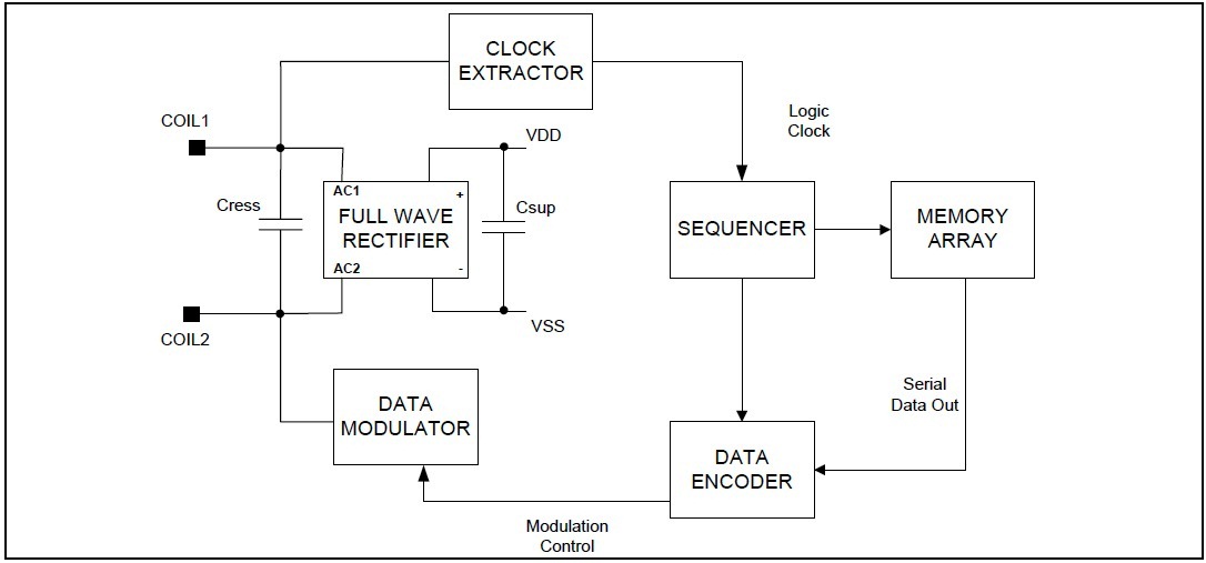
The module radiates 125KHz through its coils and when a 125KHz passive RFID tag is brought into this field it will get energized from this field. These passive RFID tags mostly consist of CMOS IC EM4102 which can get enough power for its working from the field generated by the reader.

By changing the modulation current through the coils, tag will send back the information contained in the factory programmed memory array.
Prerequisite
I hope that you already go through our tutorial, Using UART on Raspberry Pi – Python and installed pySerial.
Voltage divider
The UART TX output of EM-18 is of 5v. The input pin of Raspberry Pi GPIO is rated at 3.3v. So 5v cannot be directly given to the unprotected 3.3v input pin. Therefore we use a voltage divider circuit using appropriate resistors to bring down the voltage to 3.3V.
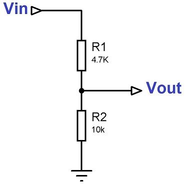
The following equation can be used for calculating resistor values,
- Vout = Vin x R2/(R1+R2)
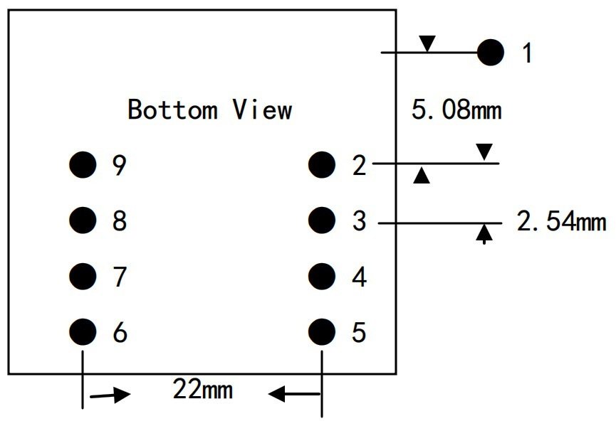
Pin Out
| Pin No. | Name | Function |
|---|---|---|
| 1 | VCC | 5V |
| 2 | GND | Ground |
| 3 | BEEP | BEEP and LED |
| 4 | ANT | No Use |
| 5 | ANT | No Use |
| 6 | SEL | HIGH selects RS232, LOW selects WEIGAND |
| 7 | TX | UART TX, When RS232 is Selected |
| 8 | D1 | WIEGAND Data 1 |
| 9 | D0 | WIEGAND Data 0 |
Components Required
- Raspberry Pi
- EM-18 RFID reader
- Buzzer (5 volt)
- Transistor BC557
- Resistors 470E, 2.2K, 4.7K, 10K
- Capacitors 100uF, 0.1uF
- Led
- Connecting wires
Circuit Diagram
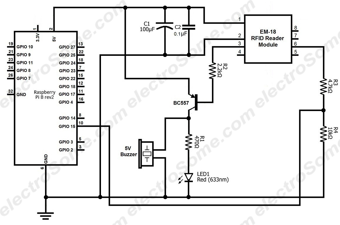
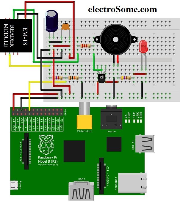
Note that the Tx pin of the reader is connected to Rx pin of Raspberry Pi through a voltage divider circuit. The 100uF and 0.1uF are for filtering the power supply. When a RFID tag of 125KHz is brought near the reader, the BEEP pin becomes LOW. This turns on buzzer and LED, mean while the RFID tag data is send through the Tx pin.
Python Program
import serial                                                  #import serial module

def read_rfid ():
   ser = serial.Serial ("/dev/ttyAMA0")                           #Open named port
   ser.baudrate = 9600                                            #Set baud rate to 9600
   data = ser.read(12)                                            #Read 12 characters from serial port to data
   ser.close ()                                                   #Close port
   return data                                                    #Return data

id = read_rfid ()                                              #Function call
print id                                                       #Print RFID
Run the above program.
Output
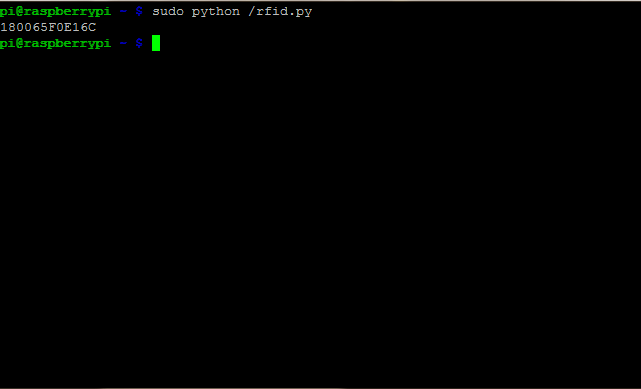
The output consists of 12 character ASCII data, where first 10 bits will be the tag number and last 2 bits will be the XOR result of the tag number which can be used for error correction. For eg : If the RFID tag number is 500097892E, output of EM-18 Reader will be 500097892E60, where 60 is 50 xor 00 xor 97 xor 89 xor 2E.
Any doubts or suggestions? Comment below.