
Contents
Matrix Keypad
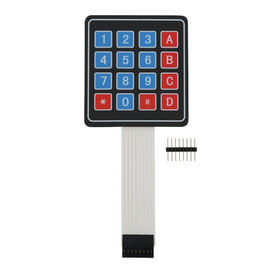
Matrix Keypads are commonly used in calculators, telephones etc where a number of input switches are required. We know that matrix keypad is made by arranging push button switches in row and columns. In the straight forward way to connect a 4×4 keypad (16 switches) to a microcontroller we need 16 inputs pins. But by connecting switches in the following way we can read the status of each switch using 8 pins of the microcontroller.

The status of each keys can be determined by a process called Scanning. For the sake of explanation lets assume that all the column pins (Col1 – Col4) are connected to the inputs pins and all the row pins are connected to the output pins of the microcontroller. In the normal case all the column pins are pulled up (HIGH state) by internal or external pull up resistors. Now we can read the status of each switch through scanning.
- A logic LOW is given to Row1 and others (Row2 – Row-4) HIGH
- Now each Column is scanned. If any switch belongs to 1st row is pressed corresponding column will pulled down (logic LOW) and we can detect the pressed key.
- This process is repeated for all rows.
If you need to save more pins of your microcontroller then you can interface keypad using the ADC module of your microcontroller.
Interfacing with 8051 Microcontroller
Circuit diagram
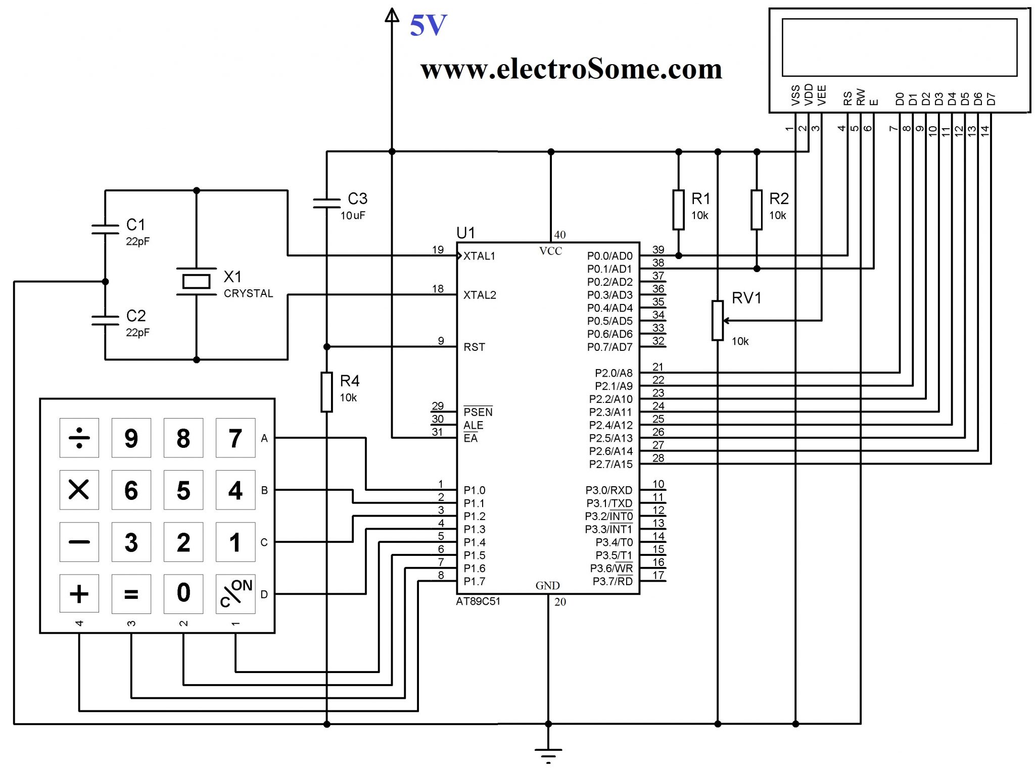
10KΩ resistor and 10μF will provide the required Power On Reset (POR) signal to the 8051 microcontroller. 12MHz crystal is used to provide required clock for the microcontroller and 22pF capacitors will stabilize the oscillations of the crystal. AT89C51 can works upto 24MHz. We can choose the required frequency by changing the crystal and clock frequency in the project settings of Keil C. Keypad is connected to the Port P1 and column inputs pins are pulled up internally. 16×2 LCD is connected to Port P2 and P0. P0.0 and P0.1 pins are pulled up externally using 10KΩ resistors since Port P0 has no internal pull up.
Keil C Code
#include<reg52.h> //including sfr registers for ports of the controller
#include<lcd.h>

//LCD Module Connections
sbit RS = P0^0;
sbit EN = P0^1;
sbit D0 = P2^0;
sbit D1 = P2^1;
sbit D2 = P2^2;
sbit D3 = P2^3;
sbit D4 = P2^4;
sbit D5 = P2^5;
sbit D6 = P2^6;
sbit D7 = P2^7;
//End LCD Module Connections

//Keypad Connections
sbit R1 = P1^0;
sbit R2 = P1^1;
sbit R3 = P1^2;
sbit R4 = P1^3;
sbit C1 = P1^4;
sbit C2 = P1^5;
sbit C3 = P1^6;
sbit C4 = P1^7;
//End Keypad Connections

void Delay(int a)
{
  int j;
  int i;
  for(i=0;i<a;i++)
  {
    for(j=0;j<100;j++)
    {
    }
  }
}

char Read_Keypad()
{
  C1=1;
  C2=1;
  C3=1;
  C4=1;
  R1=0;
  R2=1;
  R3=1;
  R4=1;
  if(C1==0){Delay(100);while(C1==0);return '7';}
  if(C2==0){Delay(100);while(C2==0);return '8';}
  if(C3==0){Delay(100);while(C3==0);return '9';}
  if(C4==0){Delay(100);while(C4==0);return '/';}
  R1=1;
  R2=0;
  R3=1;
  R4=1;
  if(C1==0){Delay(100);while(C1==0);return '4';}
  if(C2==0){Delay(100);while(C2==0);return '5';}
  if(C3==0){Delay(100);while(C3==0);return '6';}
  if(C4==0){Delay(100);while(C4==0);return 'X';}
  R1=1;
  R2=1;
  R3=0;
  R4=1;
  if(C1==0){Delay(100);while(C1==0);return '1';}
  if(C2==0){Delay(100);while(C2==0);return '2';}
  if(C3==0){Delay(100);while(C3==0);return '3';}
  if(C4==0){Delay(100);while(C4==0);return '-';}
  R1=1;
  R2=1;
  R3=1;
  R4=0;
  if(C1==0){Delay(100);while(C1==0);return 'C';}
  if(C2==0){Delay(100);while(C2==0);return '0';}
  if(C3==0){Delay(100);while(C3==0);return '=';}
  if(C4==0){Delay(100);while(C4==0);return '+';}
  return 0;
}

void main()
{
  int i=0;
  char c,p;
  Lcd8_Init();
  while(1)
  {
    Lcd8_Set_Cursor(1,1);
    Lcd8_Write_String("Keys Pressed:");
    Lcd8_Set_Cursor(2,1);
    Lcd8_Write_String("Times:");
    while(!(c = Read_Keypad()));
    p=c;
    while(p==c)
    {
      i++;
      Lcd8_Set_Cursor(1,14);
      Lcd8_Write_Char(c);
      Lcd8_Set_Cursor(2,7);
      Lcd8_Write_Char(i+48);
      Delay(100);
      while(!(c = Read_Keypad()));
    }
    i=0;
    Lcd8_Clear();
  }
}
The code consists of two user defined functions. The Delay() is used to make delay in the program execution. The Read_Keypad() reads the keypad. If any key is pressed it waits until the key is released and returns the corresponding character. If no key is being pressed it returns zero. As told before one of the pins of the row is kept at a logic 0 and the columns are checked for a logic 0. If a logic 0 is found the function returns a value according to the key pressed. This process is repeated for each row until a pressed key is found. If not found it will return zero.
This example project will show the character of key pressed and the number of times that key is pressed on the LCD screen.
while(!(c = Read_Keypad())) is used in the program to read keypad. It is a locking call as it will wait until a key is pressed and released.
Note : The lcd is interfaced using the ‘lcd.h’ header file which is to be included in the project folder. For more details about LCD interfacing please read our article Interfacing LCD with 8051 Microcontroller.
You can download Keil C files and Proteus files here…
Interfacing Keypad with 8051 using Keil C