Contents
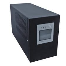
Inverter is a electrical device that converts DC Power to AC. We usually use the word Inverter for the device used in our households for mains power back up. It stores electrical energy in a battery and discharges it when need. Our household inverters mainly have two parts, Battery Charging Circuit and Inverter Circuit. Battery charging circuit charges the battery when power is available, which may be mains power, solar power or any other sources and the Inverter Circuit convert the DC power stored in the battery to AC whenever needed.
There are basically three types of inverters,
- Square Wave Inverters
- Quasi Square Wave or Modified Square Wave Inverters
- True or Pure Sine Wave Inverters
For basic requirements we can use Square Wave Inverters which is very simple, low cost and easy to make. But for driving inductive loads pure sine wave inverters are preferred. Here we are dealing with a Simple Low Power Square Wave Inverter using CD4047. It doesn’t include battery charging circuit which is present in most of the inverters. It can be used to power up to 100w.
Inverter Circuit Diagram using CD4047
Working
CD4047 is a low power IC capable of operating in either in astable or monostable mode. Here it is wired in astable mode. It works by charging a capacitor (C2) through a resistor (RV1) as in every astable multivibrators. Variable resistor (RV1) is provided for adjusting the output frequency to exact 50Hz. The time period of the oscillation is given by the relation T = 4.40*R*C. For detailed working of the IC, please refer its datasheet. CD4047 has two outputs (pins 10 and 11) which are complementary to each other. These square wave pulses are pre amplified by TIP122 transistors. This amplified current is used to switch 2N3055 transistors to drive the inverter transformer. Two 2N3055 transistors are connected in parallel to increase the current driving capabilities. The Zener Diode ZD1 and capacitor C2 is used to provide constant 9V for the IC.
When the output at pin 10 is low, pin 11 will be high Q1, Q3, Q4 turns on, current flows through the upper winding of the transformer and we will get positive half cycle output. When the output at pin 10 is high, pin 11 will be low Q2, Q5, Q6 turns on, current flows through the lower winding of the transformer and we will get negative half cycle output.
Notes
- This circuit is preferred only for driving resistive loads such as bulbs, for driving inductive loads it is better to use pure sine wave inverters.
- A 12V Lead Acid Battery can be used as the power source. If you want to operate this circuit for long time, use a battery having higher Ah ratings.
- For the inverter transformer, use a normal 12-0-12 transformer, use its secondary as primary and primary as secondary.
- If you don’t get a 10A transformer, use a 5A instead provided that the max power output decreases proportionally.
