
Contents
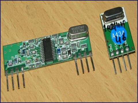
A wireless radio frequency (RF) transmitter and receiver can be easily made using HT12D Decoder, HT12E Encoder and ASK RF Module. Wireless transmission can be done by using 433Mhz or 315MHz ASK RF Transmitter and Receiver modules. In these modules digital data is represented by different amplitudes of the carrier wave, hence this modulation is known as Amplitude Shift Keying (ASK). Radio Frequency (RF) transmission is more strong and reliable than Infrared (IR) transmission due to following reasons :
- Radio Frequency signals can travel longer distances than Infrared.
- Only line of sight communication is possible through Infrared while radio frequency signals can be transmitted even when there is obstacles.
- Infrared signals will get interfeared by other IR sources but signals on one frequency band in RF will not interfeared by other frequency RF signals.
Transmitter Circuit Diagram

HT12E Encoder IC will convert the 4 bit parallel data given to pins D0 – D3 to serial data and will be available at DOUT. This output serial data is given to ASK RF Transmitter. Address inputs A0 – A7 can be used to provide data security and can be connected to GND (Logic ZERO) or left open (Logic ONE). Status of these Address pins should match with status of address pins in the receiver for the transmission of the data. Data will be transmitted only when the Transmit Enable pin (TE) is LOW. 1.1MΩ resistor will provide the necessary external resistance for the operation of the internal oscillator of HT12E.
Receiver Circuit Diagram
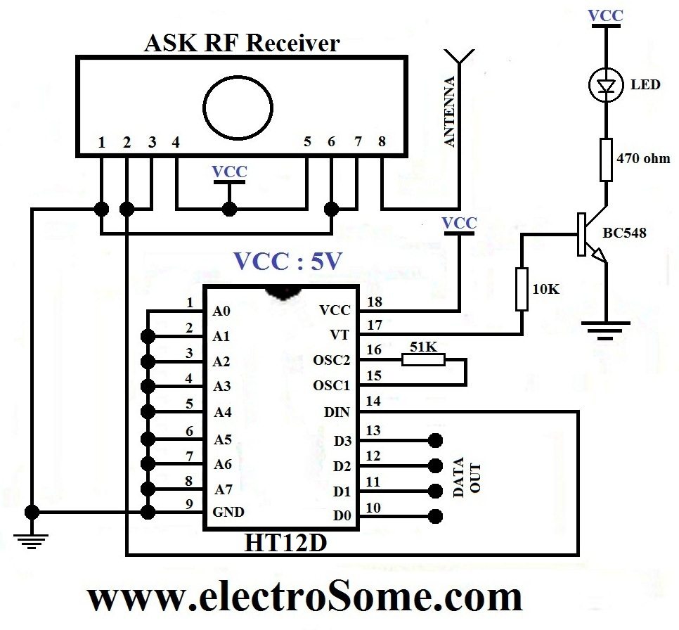
ASK RF Receiver receives the data transmitted using ASK RF Transmitter. HT12D decoder will convert the received serial data to 4 bit parallel data D0 – D3. The status of these address pins A0-A7 should match with status of address pin in the HT12E at the transmitter for the transmission of data. The LED connected to the above circuit glows when valid data transmission occurs from transmitter to receiver. 51KΩ resistor will provide the necessary resistance required for the internal oscillator of the HT12D.
