

Wireless Transmitter and Receiver using ASK RF Module
Contents
A wireless radio frequency (RF) transmitter and receiver can be easily made using HT12D Decoder, HT12E Encoder and ASK RF Module. Wireless transmission can be done by using 433Mhz or 315MHz ASK RF Transmitter and Receiver modules. In these modules digital data is represented by different amplitudes of the carrier wave, hence this modulation is known as Amplitude Shift Keying (ASK). Radio Frequency (RF) transmission is more strong and reliable than Infrared (IR) transmission due to following reasons :
- Radio Frequency signals can travel longer distances than Infrared.
- Only line of sight communication is possible through Infrared while radio frequency signals can be transmitted even when there is obstacles.
- Infrared signals will get interfeared by other IR sources but signals on one frequency band in RF will not interfeared by other frequency RF signals.
Transmitter Circuit Diagram

HT12E Encoder IC will convert the 4 bit parallel data given to pins D0 – D3 to serial data and will be available at DOUT. This output serial data is given to ASK RF Transmitter. Address inputs A0 – A7 can be used to provide data security and can be connected to GND (Logic ZERO) or left open (Logic ONE). Status of these Address pins should match with status of address pins in the receiver for the transmission of the data. Data will be transmitted only when the Transmit Enable pin (TE) is LOW. 1.1MΩ resistor will provide the necessary external resistance for the operation of the internal oscillator of HT12E.
Receiver Circuit Diagram
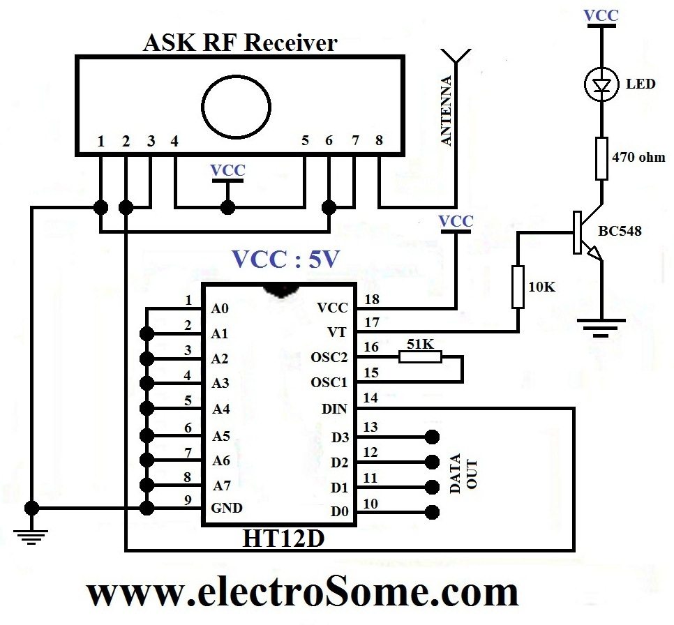
ASK RF Receiver receives the data transmitted using ASK RF Transmitter. HT12D decoder will convert the received serial data to 4 bit parallel data D0 – D3. The status of these address pins A0-A7 should match with status of address pin in the HT12E at the transmitter for the transmission of data. The LED connected to the above circuit glows when valid data transmission occurs from transmitter to receiver. 51KΩ resistor will provide the necessary resistance required for the internal oscillator of the HT12D.


This is only for digital signals.
Thank u.
How if I want to transmit an analog signal?
Sir plz tell me
how to give the input message
Hello Sir, please can I transmit *AUDIO* signals using the Encoder (HT12E) and Decoder (HT12D) pair?
Sir I want to use 2 transmitters at different locations . Transmitter-1 using b0, b1 input pins & Transmitter-2 using b2, b3 input pins & 1 receiver using these two transmitter. will it work or how these can be used.
Thanks & Regards
Are we limited to 56 addresses?
hi everybody, i really want to know how to find out presence of this kind of reciever circuit in which is situated in any cabinet.,please
sir can it work if we want to transmit a low ac voltage signal
or sir can you help me in one of my project ,i want to transmit a voltage signal that will be received on a receiver wirelessly . so sir what i use for this work
what is out voltage and current
what is out voltage?
Sir I have a receiver bought from the market I want to get the signal received history in my computer how can I get this .
I would like to make a quadcopter…..could u please help
our group is doing project on home automation, hence we are using different sensors like IR, PIR, MQ6, etc for security purpose.we have to send the output of these sensors to a single place inside home and we thought of using 3 rf transmitters and sensor and 1 rf reciever to recieve all signal. the problem is reciever receives data from only one transmitter and not from other two.plz help me out sir.our project is struct in midway. waiting for reply
Sir i wants to make a quadocopter which controlled by rf controller plz help me
hello sir.. can i know the transmission rate of the module? how many bits can it transmit in 1 second.. i am trying to transmit an image using this.. is it possible?
is it possible to transmit image data using this transmitter receiver pair?
can i use transmitter & receiver in voice recognizing quadcopter
Try searching internet, you will get a lot of circuits for that.
Catching unwanted signal or noise ?
Yes, wattage is not a problem there.
how to make a remote control car ? With transmeter and reseaver can you give me a diagram. Pleeeeeeese
Sir,
We have a Rf trans receiver set working on 12V, Learning code is coded. Now unwanted signals it is catching and receiver get activated on un wanted times. Can you please suggest some remedy
I COULDNOT FIND THE 1.1 M AND 51 K RESISTOR SO AM USING 100K 1 M 39K AND 12 K ATTACHED TO GET THE DESIRED VALUES BUT LET ME MAKE SURE SOMETHING IS THE WATTAGE OF RESISTORS 1/4 W?
You can use one microcontroller for adc and transmitting data. Use another microcontroller to receive that data and to drive lcd display.
Sorry, please elaborate your project. You can use above circuit to transmit small data.
Sir,
How to connect LCD display to transmitter and reciver?
And how to connect transmitter to analog to digital converter.
Sir,
I want to connect calculator to transmitter how to connect it?Can I use any transmitter with any reciver?
If you need 400 meters, you should some other wireless transmitter.
It is 100m as per the specification of the module.
Sir, I would like to use the circuit as water tank controller with distance about 400 mtrs. Is it possible?
how long or distance it can pass data?
More than one transmitter of same frequency won’t work simultaneously at the same time. You may use 2 different frequencies like 315MHz and 434MHz. Or you can transmit by time splitting.
Yes, you can try….
Yes, it is possible and is very easy. Just use a transistor to drive that buzzer or relay.
You may use some digital circuit to send 8 bits vai 4 channels.
I am using three transmitter and three receiver sets, but now every receiver is showing no input signals. Each set of tx and rx are set with different pins grounded. Pls can you explain it. Which mode of signal transmission should I use. or how can I solve this problem.
i wana make the transmitter and receiver any body help mee???
can this model be used with a quadcopter?
hello, I just want to transfer Logic 0 or 1 to control a Buzzer/ Relay with this circuit with out adding the encoder /decoder. Is it possible??
Hi. It’s any IC like HT12E/D that can take 6/8 parallel inputs? I can’t found HT600s series in my country :/
I need to send 6 or 8 bits via RF, and I dont want to use uC.
Thanks!
Sorry, I am not sure about it.
To make it in Vietnam, I see that HT12E and HT12D are not being sold in Vietnam. I am going to try PT2262 and PT2272 as alternatives. Do you think that circuit would still work even though I use them instead of HT12E and HT12D?
I don’t think. How it will work if antenna is shorted to ground ?
Better to try with different metals, sorry I am not sure which will work fine.
It is good to use float switch or ac sensing.
I haven’t yet used the 4 pin one. It will be another design that’s all.. Even in 8 pin. only 4 pins are used. VCC, GND, DATA and ANT.
Best way to transmit it serially.
I have a 434 MHz RF Receiver (8-pin) module. I am finding the ANT pin is shorted to its adjacent GND pin. Is it normal?
sir, what is the difference between rf receivers with 4 pins and 8 pins?? Thnx
sir,
I have 12 different data lines from micro controller, I need to transmit this wireless, Please suggest a method.
Above circuits are 100% percentage working. The receiver side LED will glow when the transmitter is connected to the receiver. Make sure that all resistor values and connections are correct.
I don’t think you can do it using these modules.
I am using this module only to transmit data using gesture controlling glove. Made all the connections exactly as mentioned above.Still it’s not working. If I send high on all four pins of encoder ic, there is no output voltage at the data lines of decoder which I checked by connecting an LED to it
What could possibly be the problem ?
Please help !
sir,
is there any way that i can compare the signal strength at the receiver side with a reference point.
thank you sir.
3 pin in transmitter doesn’t make a great difference !!
3 pin Gnd,Data,Vcc .. Antenna is a hold at the corner !
4 pin in reciever also the same case !
4 pin Gnd,Data,Vcc,Antenna !
Difference is made in the way by coupling them !!
Just take a look at 8 pin they are coupled !!
Yes, it is possible.
I think you can make it using the above circuit, L293D motor driver, dc motors etc.
Delay time ?? I think it is fast enough. You can even transmit low baud rate UART wirelessly.
Most probably, it will receive the signal with higher strength. But I think some times it may not receive anything due to interference, especially when they are close enough.
Sir, can i use rf modelule and interface with at89c51 without using decoder and encoder?
This model is working.
Thanks for saving my project, sir.
hallo sir
i want to make rf 4 wheel car for roborace
wireless
so plz suggest me what components will need?how to make pcb connection plz provide circuit diagram plz i need ur help my id is [email protected]
sir how can i reduce the delay time
(time between i/p to transmitter nd o/p at the receiver)
plzz help me out
nd thnx
If I have two identical rf receivers placed at different distances from the rf transmitter.(let’s assume they’re differing by quite a distance. They’re not very close.) Will the nearest receiver receive a signal with higher strength or will both receive the same strength? If yes, can I compare the signal strengths, a logical comparison to find out which is stronger using the values received by the receivers.Thanks.!
It is the address.. I set all address to 0, that’s why it is grounded. You can change it as your wish.
What ?
Receiver will work only with 5V supply. Don’t provide 12V.
No speaker, no motor,,
Maximum output current capability of HT12D is only 1.6mA.
Yes, you can use like that … no problems.
Better to use a small microcontroller. Otherwise you have to implement a digital circuit using the logic. You can use L293D for driving the motor.
Why you need 4 motors ? If it is only 2 motors and a castor wheel then the solution will become very simple.
If you want to operate it only during the running time of dynamo, you can connect it after filtering and regulating.
sir, why are 1-9 pins of ht12d grounded?
if my receiver is at 12 volts than what voltage should i apply to the transmitter ckt???
plz help me out.
That’s a good idea.
My opinion is refer to the data sheet of T2(315mhz), If it works on 5v input then it’ll surely work. Because from R1, you’ll get 5v only.
This circuit is 100% working. Thanks! Thanks!
Sir, can you tell what is the current at the output?
I want to run a 5v motor or speaker at output.
so thats mean, we can use 2 pair like this:
T1 transmitter(433mhz) will send data to R1 receiver(433mhz) and then T2 tranmitter(315mhz) can take input from R1 receiver(433mhz) and again T2 transmitter(315mhz) will send data to R2 receiver(315mhz) .
so can i use this flow in our project:
T1—>R1—>T2—->R2
?????
Please help me on this.
Thank you sir.
hello sir;
i wanted to connect 4 dc, 12V motors(wireless);for d tyres so dat d car can turn left nd right,foward nd backward;
and 1 on-off switch(wireless) for another 12V motor;
how can i use the data lines.????
Sir how can i use 433 rf and ht12 e and d to a 12volts dynamo? How can i connect? Tnx a lot.
If you want to use 2 pairs at a time, you should use different frequencies 315Mhz and 434Mhz.
Yes, you can.
Hi sir,
Thank you for this information,
Please help me on this,
how can I use 2 transmitter and 2 receiver with ht12e/d,
and how can I enable and disable TE pin according to first transmitter and 2nd transmitter,
and how can we use A0-A7 pin for both transmitter and receiver.
please help me on this,
I am not able to use 2 transmitter and 2 receiver for increasing the range .
Thank you buddy . I really need this circuit .
sir can i use 433 rf transmitter and receiver with ht12 e and ht12 d? tnx
Transmitter 12V…. Receiver works with 5V.
Thanks for your feedback.
HT12D / HT12E is not a programmable IC. No need of programs.
Whats the voltage to get maximum range?
Its not a programmable IC
#include
#include
__CONFIG(0X3F32);
#define _XTAL_FREQ 12000000
#define RS RB1 //LCD PINS
#define E RB0
#define DATA PORTD
#define B1 RB2
#define RELAY RB3
#define R1 RC0 //ROW-output
#define R2 RC1
#define R3 RC2
#define R4 RC3
#define C1 RB7 //COL inputs
#define C2 RB6
#define C3 RB5
#define C4 RB4
char *s;
int k,o,t,h,th;
char in[4];
unsigned long int i1=2215486;
unsigned char value[4][4]= { ‘1’,’2′,’3′,’4′,
‘5’,’6′,’7′,’8′,
‘9’,’A’,’B’,’C’,
‘D’,’E’,’F’,’0′ };
char p[4]={‘1′,’2′,’3′,’4’};
void cmd(unsigned char c)
{
DATA=c;
RS=0;
E=1;
__delay_ms(10);
E=0;
}
void data(unsigned char d)
{
DATA=d;
RS=1;
E=1;
__delay_ms(10);
E=0;
}
void printxy(const char *w,int r ,int c)
{
int i=0;
if(r==1)
{
for(i=c;i<*w!='';i++)
{
cmd(0x80+i);
data(*w);
w++;
}
}
if(r==2)
{
for(i=c;i<*w!='';i++)
{
cmd(0xc0+i);
data(*w);
w++;
}
}
}
void digit4xy( unsigned int digit,int r,int c1)
{
int c=c1-1;
o=digit%10;
t=(digit%100)/10;
h=(digit%1000)/100;
th=(digit%10000)/1000;
if(r==1)
{
cmd(0x80+c);
data(th+0x30);
c++;
cmd(0x80+c);
data(h+0x30);
c++;
cmd(0x80+c);
data(t+0x30);
c++;
cmd(0x80+c);
data(o+0x30);
}
if(r==2)
{
cmd(0xc0+c);
data(th+0x30);
c++;
cmd(0xc0+c);
data(h+0x30);
c++;
cmd(0xc0+c);
data(t+0x30);
c++;
cmd(0xc0+c);
data(o+0x30);
}
}
unsigned int getkey(void)
{
int row,co,dummy,flag=0;
R1=R2=R3=R4=0;
//__delay_ms(1000);
R1=1;R2=0;R3=0;R4=0;
{
//__delay_ms(10);
if(C1==1){
while(C1==1);
return '1';
}
if(C2==1){
while(C2==1);
return '2';
}
if(C3==1){
while(C3==1);
return '3';
}
if(C4==1){
while(C4==1);
return 'A';}
}
R1=0;R2=1;R3=0;R4=0;
{
//__delay_ms(10);
if(C1==1){
while(C1==1);
return '4';}
if(C2==1){
while(C2==1);
return '5';
}
if(C3==1){
while(C3==1);
return '6';
}
if(C4==1){
while(C4==1);
return 'B';
}
}
R1=0;R2=0;R3=1;R4=0;
{
//__delay_ms(10);
if(C1==1){
while(C1==1);
return '7';}
if(C2==1){
while(C2==1);
return '8';
}
if(C3==1){
while(C3==1);
return '9';
}
if(C4==1){
while(C4==1);
return 'c';
}
}
R1=0;R2=0;R3=0;R4=1;
{
//__delay_ms(10);
if(C1==1){
while(C1==1);
return '*';
}
if(C2==1){
while(C2==1);
return '0';
}
if(C3==1){
while(C3==1);
return '#';
}
if(C4==1){
while(C4==1);
return 'D';
}
}
return 0xff;
}
int keypressed()
{
int dummy;
do
{
__delay_ms(100);
dummy=getkey();
}while(dummy==0xff);
return dummy;
}
char *getstring(int length)
{
static char f[16];
int i=0;
for(i=0;i<length;i++)
{
f[i]=keypressed();
cmd(0x80+i);
data(f[i]);
}
f[length]='';
return f;
}
void serial_initi()
{
//TXSTA REG
CSRC=0;TX9=0;TXEN=1;SYNC=0;BRGH=1;
TRMT=1;
TXIE=0;
RCIE=1;
//RCSTA REG
SPEN=1;
RX9=0;
SREN=0;
CREN=1;
SPBRG=25;
}
void uart_write(const char d)
{
while(TXIF==0);
TXREG=d;
//__delay_ms(50);
}
void uart_string(const char *w)
{
do
{
uart_write(*w);
w++;
}
while(*w!='');
}
void digit4_uart(unsigned int digit)
{
int a[4];
//int a1=digit;
a[0]=digit%10;
a[1]=(digit%100)/10;
a[2]=(digit%1000)/100;
a[3]=digit/1000;
uart_write(a[3]+0x30);
uart_write(a[2]+0x30);
uart_write(a[1]+0x30);
uart_write(a[0]+0x30);
}
char uart_read()
{
while(RCIF==0);
return RCREG;
}
char uart_ready_send()
{
return TXIF;
}
char uart_ready_read()
{
return RCIF;
}
char uart_read_string()
{
int i=0;
do
{
s[i]=uart_read();
i++;
}while(uart_read()!='');
return *s;
}
void uart_enter()
{
uart_write(0x0d); //
uart_write(0x0a); //
}
void gsm_initi()
{
uart_string(“AT”);
uart_enter();
uart_string(“AT+CMGF=1”);
uart_enter();
__delay_ms(100);
}
void send_message(const char *msg)
{
gsm_initi();
//uart_string(“AT+CMGS=”);
//uart_write(‘”‘);
//uart_string(“9597422089”);
//__delay_ms(300);
uart_write(‘”‘);
uart_write(0x0a);
__delay_ms(300);
uart_string(msg);
__delay_ms(300);
uart_enter();
uart_write(0x1a); //control z
__delay_ms(300);
}
unsigned int random()
{
while(B1==1)
{
i1++;
digit4xy(i1,2,7);
}
__delay_ms(200);
return i1;
}
char *otp_string()
{
int otp=0;
otp=random();
digit4xy(otp,2,6);
char a[4];
a[0]=otp%10;cmd(0xc0);
data(a[0]);
a[1]=(otp%100)/10;cmd(0xc1);
data(a[1]);
a[2]=(otp%1000)/100;cmd(0xc2);
data(a[2]);
a[3]=(otp%10000)/1000;
cmd(0xc3);
data(a[3]);
return a;
}
void lcd_initi()
{
cmd(0x38);
cmd(0x06);
cmd(0x0c);
cmd(0x01);
//cmd(0x0e);
}
void main()
{
TRISD=0X00;
TRISC=0B10110000;
TRISB=0XF0;
lcd_initi();
serial_initi();
int i=0,op=3333;
RELAY=0;
while(1)
{
printxy(“OTP TEST”,1,2);
//uart_write(‘k’);
//digit4_uart(op);
char k;
k=random(); //getting OTP as string
digit4xy(k,2,1);
//gsm_initi();
uart_string(“AT”);
uart_enter();
__delay_ms(50);
uart_string(“AT+CMGF=1”);
uart_enter();
__delay_ms(50);
uart_string(“AT+CMGS=”);
uart_write(‘”‘);
uart_string(“9597422089”);
uart_write(‘”‘);
uart_enter();
__delay_ms(50);
uart_string(“YOUR OTP IS:”);
//uart_enter();
__delay_ms(50);
digit4_uart(k);
uart_write(0x0a);
__delay_ms(50);
uart_write(0x1a); //control z
cmd(0x01);
printxy(“MSG SEND”,1,1);
__delay_ms(500);
printxy(” TYPE PASSWORD”,1,1);
char check[4];
check[3]=k%10;
check[2]=(k%100)/10;
check[1]=(k%1000)/100;
check[0]=k/1000;
__delay_ms(500);
for(i=0;i<4;i++)
{
in[i]=keypressed();
cmd(0xc0+i);
data(in[i]);
}
if(in[0]==th+0x30&&in[1]==h+0x30&&in[2]==t+0x30&&in[3]==o+0x30)
{
cmd(0x01);
printxy("MATCHED",1,1);
RELAY=1;
//continue;
}
else
{cmd(0x01);
printxy("NOT MATCHED",1,1);
RELAY=0;
break;
}
__delay_ms(500);
cmd(0x01);
}
}
nice tutorial
Hello sir,
How can i flash hex file in HT12D/E ?
i am using universal programmer IC kit box, but i am not able to flash image,
can u plz help me, which kit box , we have to use ?
Sorry we don’t have it.
The transmission range varies with the applied voltage.
hey sir .!!! will you plz give me the code of transmitter and reciever with pic microcontroller ??
Argentina. Nevermind, i found a pair. It doesn’t matter what voltage I use (3-12)V, i will always use a 1.1M ohm resistance in the ht12e circuit?
You can connect it directly to the above circuit.
I think you can use the modules directly.
Just try it .. but it might not work with 55K.
i want to operate wireless buzzer on off using rf module
sir how to make 1ch transmitter and receiver without using encoder and decoder,microcontroller etc. ic’s
give me solution for this
Sir, at receiver, 15-16 pin requires 51k can I use 55k?
Which is your country ?
Yes, you can use it.
Should I use the LM 7805 ic for receiver to get 5 volt?
I think you need to invert the output of receiver module before connecting it to uart input.
I am doing a home automation project and it requires 2 89c51. One 89c51 has been interfaced with the 434mhz transmitter module (ie tx pin of 89c51 is connected to data in of transmitter module) and the other 89c51 has been interfaced with the receiver module( rx pin of 89c51 is connected to data out of receiver module).
So if I configure the IC with the lowest baud rate (ie1200), will it work?
Yes.. you can use it.. but you should use lowest baud rate.
Yes.. you can use 6V adaptor. .with a diode in series..
For protecting circuit from surges.. you can use MOV (Metal Oxide Varistor)
It is hard to find the pair of HT12 in my country. Is it possible that I could replace them with some other decoder/encoder Integrated circuit?
Can these modules support direct serial communication with 2 89c51, one on the transmitter side and the other on the reciver side???
If otherwise I connect it to 220 V previously adapted to lets say 6 V, should i use a voltage regulator(adaptate to 5 V) to protect the circuit against electrical surge(diodes won’t work)? Or the 6 V adaptator would do the job?
You can use it .. by changing address.
But simultaneous operation of all transmitters in the same vicinity will not work.
Nop.
Good idea!. I hope the extra 0.3 V won’t screw the circuit 😛
Just put a diode in series.. it will drop 0.7V.
Yes, it will be possible.. But use lowest baud rate.. 2400.
Do i have to make any change to the circuit if the receiver circuit is supplied with a 6 Volts or 4.5 VCC(it’s because i can only get batteries of 1.5 Volts, so I plan to put 3 of them together for 4.5 or 4 for 6 volts. I don’t want to craft a voltage divider subcircuit or use a lm317 voltage regulator.
Sir can we send 8bit uart data by pic16f877a by RF communication……if possible then how..
You can use above circuit for that.
Thanks for the suggestion.
I want to make wireless device which can receive the data upto 90 degree upto 20 meter. can any body help?
I think you should make a video of completed circuit board, it’ll help everyone.
Thanks
You may use a 315Mhz and a 434MHz for that. But it is better to send 8 bit data as 2 parts sequentially with 1 pair. You may also use UART with low baud rate.
Sir can we use 2 pair of 4 bit rf transmitters for 8 bit data transmission
Make sure that you are using correct oscillator resistors.
Yes, exactly.
Sorry, I haven’t yet used ST12.
My Valid reception LED (one in line with the transistor) is also not turning on to say there is a connection between the boards, what can this be a sign of
what does that mean exactly? does this mean that, if I for instance, apply a Constant 5 Volts to a digital input of the encoder, does this mean the output on the reciever will be a 5V output (i.e. is the digital equivalent of logic 1 – 5V)
can you help me by making a wireless transmitter and receiver using st12 ?
Sorry, I haven’t yet used that module.
Sir i have purchased the Transmitter and receiver . the problem i just noticed is that the one i have got has 3 pins in its transmitter and 4 in its receiver while in the block diagram it has 4 and 8 pins respectively.But it operates on 433 Mhz.Will it work .How can i connect the pins. Need your help .
This is digital transmitter and receiver..
can this module transmit a 0-9V signal?
It can transmit more than 100 meters with proper antennas.
how much distance it can travel
mai i know the range of transmitter
Above circuits are 100% working… Make sure that you are using correct oscillator resistors..
Good day,pls i did my own circuit but the transmitter and the receiver are not communicating. how can i troubleshoot the problem pls? and i must get it done today! someone pls help
Yes ofcourse..
hi ..
can we use 8pin switch for the address code rather then grounding all?
No, the above circuit will works at 315MHz or 434MHz….
sir shall we use ordinary radio as a receiver tuned to the particular frequency?
sir,,, if we use two set of rf module at same place it is not working one RF receiver will off..They are getting interfere with each other.how we can use two rf module at same place…pls help
Is this transmitter module compatible with your design?
www (dot) alexan (dot) com (dot) ph/downloads/alexan_rf (dot) pdf
This modules has 8 pins for the transmitter while what you used with your design only has 4 pins. Can youhelp us in implementing this module (attached link) with your design? What should we do with the transmitter module connections?
Are we going to have problems with this module (attached link) ?
Use correct resistor values otherwise it may not work.. use 1Mohm or 1.1Mohm for ht12e..
Hi,
I have made a similar circuit using 434mhz module. I have used ht12e and ht12d ICs. Between osc1 and osc2 I have used 750k resistor for ht12e and a 33k resistor for ht12d. I have kept pin 3 of receiver (linear o/p) open. And I have not yet connected antenna in either Tx or Rx. Everything else is the same as in your blog. But my circuit is not at all working even if i keep Tx and Rx 5cm apart! Please guide me to solve my problem! Thanks!
I don’t get your question.
You can buy this module here :
http://www.ebay.in/itm/ASK-RF-Transmitter-and-Receiver-module-/221553116682
Can this module be used with the ciruits in this page? The Transmitter have 8 pins instead of four.
Use an ethernet or wifi module.
sir i want to need some guidance to controll my pic16f through internet.sir help me please
Does the Valid Reception LED is working ?
My mail id : [email protected]
For asking doubts use our forum : http://electrosome.com/forum/
or this commenting system.
all data out pins are always high even if i try to have all the data in pins graounded. can i have your email address sir?
Hello, it is 100% working… you might have made some mistake ..
You can also buy the completed item through eBay : http://www.ebay.in/itm/ASK-RF-Transmitter-and-Receiver-module-/221538214585
i imitated your design and i cant have it working :(( i placed an led on D0 and it’s just always high. the led on the collector doesnt even light up it just sometimes blink 🙁 please help me
hmm … .i was thinking personally………..
sir , thank you so much for your help …….
Try using ADC… and DAC.. before that find the bandwidth of your transmitter and receiver by using a CRO and Function Generator.
thank you so much for this article .>>>>>> this _ is _ *** _working……..
it’s awesome…………………………….. but is there any way to transmit analog audio signal through a Digital way using HT12E , Sir ?????????????
Yes, it is 100% working
is this really working?
Actually, I don’t know.. They might be simpler and low cost..
These are readymade RF module available in the market..
why ask modulation is used in RF modules when they are susceptible to noise?
how strong are these ic’s are they the same