

Interfacing LCD with Arduino Uno
Contents
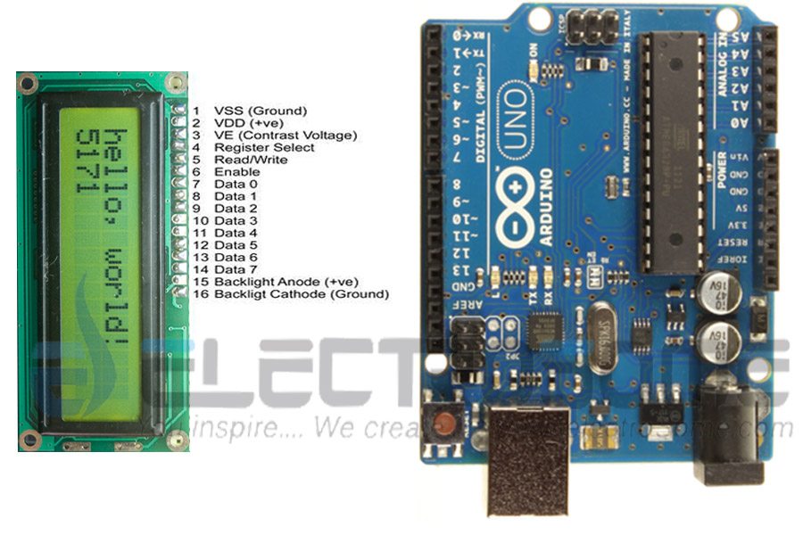
16×2 character LCD display is a very basic LCD module which is commonly used in electronic projects. 16×2 means it can display 2 rows of 16 characters (columns). Its other variants such as 16×1, 16×4 etc are also available. These LCDs are usually made using HD44870 compatible controllers. In this tutorial we will see how to interface a 16×2 Character LCD display with Arduino Uno development board. Arduino provides built in libraries for interfacing HD44870 compatible LCDs.

In a 16×2 character LCD display, there are 16 pins. First two pins VSS and VDD are for providing power to the display. Connect these pins to the GND and 5V supply pins in the Arduino Uno. 3rd pin of the LCD is named as Vo which is used for adjusting display contrast. We can use a 10KΩ preset for that, connect variable end to Vo and fixed ends to VSS and VDD. 4th pin RS is the Register Select pin which is used to multiplex the data and command information send to the LCD module. Data information is the ASCII value of the information to be displayed on the LCD and the command information will contain instructions such as the position in which the data is to be displayed etc. These two information will be multiplexed using pin RS and will send through DB0 – DB7 pins of LCD. If RS is high, then DB0 – DB7 will contain data information and when it is LOW then these lines will contain command information. 5th pin R/W is Read or Write pin which will determine whether the data is to be written or it is to be read from the LCD display. HIGH value of this pin will indicate the data is read from the display and LOW value indicates writing information to the display. Normally we need only writing values to the display, so we usually tie RW to GND. 6th pin E is the Enable pin of LCD. High value on E will indicate valid information on DB0 – DB7 pins. We can power the LCD’s back-light LED using last two pins.
The interface between this LCD and Arduino can be 8 bit or 4 bit and the difference between them is in how the data or commands are send to LCD. In the 8 bit mode, 8 bit data and commands are send through the data lines DB0 – DB7 and data strobe is given through E input of the LCD. But 4 bit mode uses only 4 data lines. In this 8 bit data and commands are splitted into 2 parts (4 bits each) and are sent sequentially through data lines DB4 – DB7 with its own data strobe through E input. The idea of 4 bit communication is introduced to save pins of the controller. You may think that 4 bit mode will be slower than 8 bit. But the speed difference is only minimal. As LCDs are slow speed devices, the tiny speed difference between these modes is not significant. Just remember that Arduino Uno is operating at high speed in the range of 16MHz and we are viewing LCD with our eyes. Due to Persistence of Vision of our eyes we will not even feel the speed difference.
Arduino LiquidCrystal Library
Arduino LiquidCrystal library enables us to interface LCDs having Hitachi HD44780 or compatible controllers with Arduino Boards. This library can work either in 8-bit or 4-bit mode depending upon how we initialize LCD connections.
LiquidCrystal()
This function is used to initialize connections of LCDs. It creates a variable of type LiquidCrystal. By proper initialization of connections, we can control LCD either in 8-bit or 4-bit mode.
Syntax :
LiquidCrystal(RS, EN, D4, D5, D6, D7)                      // 4-bit mode
LiquidCrystal(RS, RW, EN, D4, D5, D6, D7)                  // 4-bit mode
LiquidCrystal(RS, EN, D0, D1, D2, D3, D4, D5, D6, D7)      // 8-bit mode
LiquidCrystal(RS, RW, EN, D0, D1, D2, D3, D4, D5, D6, D7)  // 8-bit mode
Description
- RS indicates the Arduino pin number to which LCD RS (Register Select) is connected.
- EN indicates the Arduino pin number to which LCD EN (Enable) is connected.
- RW indicates the Arduino pin number to which LCD RW (Read / Write) is connected
- D0 – D8 indicates Arduino pin numbers to which LCD data pins are connected.
Note 1 : D0 – D3 pins are optional, if omitted the LCD will be controlled in 4-bit mode.
Note 2 : RW pin is also optional. RW pin is used to indicate Read or Write operation is to be performed. Since LCD is an output device, we usually write data to it, so RW pin can be tied to ground instead of connecting it to Arduino.
Example :
LiquidCrystal lcd(12, 11, 10, 5, 4, 3, 2);
Where lcd is the variable.
begin()
This function initializes the interface to LCD display and it also sets the size (columns and rows) of the display. It should be called before any other LCD library functions. The parameters of this function will be the dimensions of the display, that is the number of rows and columns.
Syntax :
lcd.begin(columns,rows);
Where,
- lcd is a variable of type LiquidCrystal used while defining LCD connections
- columns is the number of columns that the display has
- rows is the number of rows that the display has
clear()
This function clears the LCD display and sets the cursor to upper left corner.
Syntax :
lcd.clear();
home()
Sets the cursor to upper left corner.
Syntax :
lcd.home();
setCursor()
This function will set the position of the LCD cursor. That means the location in which the subsequent data is displayed on the screen. In this function we can specify in which column and row we want to display our data. Note that the numbering of columns and rows are starting from 0.
Syntax :
lcd.setCursor(column, row);
write()
Writes a character to LCD display and returns the number of bytes written.
Syntax
lcd.write(Data);
Where Data is the character to be written to LCD.
print()
Writes text to LCD display and returns the number of bytes written.
Syntax :
lcd.print(Data);
lcd.print(Data, Base);
Where,
Data is the text to be printed. It can be char, byte, int, long or string.
Base is an optional parameter which can be used while printing numbers. It can be BIN (for binary), DEC (for decimal), OCT (for octal) and HEX (for hexadecimal).
cursor()
This function displays the cursor (underscore) on the LCD display at a position in which next character will be written.
Syntax :
lcd.cursor();
noCursor()
This function hides the LCD cursor.
Syntax :
lcd.noCursor();
blink()
This function displays blinking cursor on LCD display. This is useful in some cases where user input is required.
Syntax :
lcd.blink();
noBlink()
This function turns off the blinking cursor.
Syntax :
lcd.noBlink();
noDisplay()
This function turns off the LCD display without lossing the contents in the LCD.
Syntax :
lcd.noDisplay()
display()
Turns on the LCD when it is in off state by noDisplay().
Syntax :
lcd.display();
scrollDisplayLeft()
Scrolls the contents of LCD display left by one position.
Syntax :
lcd.scrollDisplayLeft();
scrollDisplayRight()
Scrolls the contents of LCD display right by one position.
Syntax :
lcd.scrollDisplayRight();
autoscroll()
This function turns on the automatic scrolling of LCD contents. If the current text direction is Left to Right (default), the display scrolls to left and if the current text direction is Right to Left, the display scrolls to right. You can change the current text direction using functions leftToRight() and rightToLeft() as described below.
Syntax :
lcd.autoscroll();
noAutoscroll()
Turns off the automatic scrolling of the LCD set by autoscroll().
Syntax :
lcd.noAutoscroll();
leftToRight()
Calling this function sets the direction of text written to the LCD as Left to Right (default). This implies that the subsequent characters written to LCD will go from Left to Right without affecting previously written characters.
Syntax :
lcd.leftToRight();
rightToLeft()
Calling this function sets the direction of text written to the LCD as Right to Left. This implies that the subsequent characters written to LCD will go from Right to Left without affecting previously written characters.
Syntax :
lcd.rightToLeft();
createChar()
This function creates a custom character for use on the LCD. Each character is created using 5×8 pixel matrix. We need to define it as a byte array. We can create up to 8 custom characters.
Syntax :
lcd.createChar(Number, Data);
Where,
Number is the reference number of custom character to be created, it ranges from 0 to 7.
Data is byte array indicates character’s pixel data.
Example :
byte smiley[8] = {
   B00000,
   B10001,
   B00000,
   B00000,
   B10001,
   B01110, B00000,
};
void setup() {
   lcd.createChar(0, smiley);
   lcd.begin(16, 2);
   lcd.write(byte(0));
}
Note : You should typecast custom characters as byte as shown above if it is not in a variable.
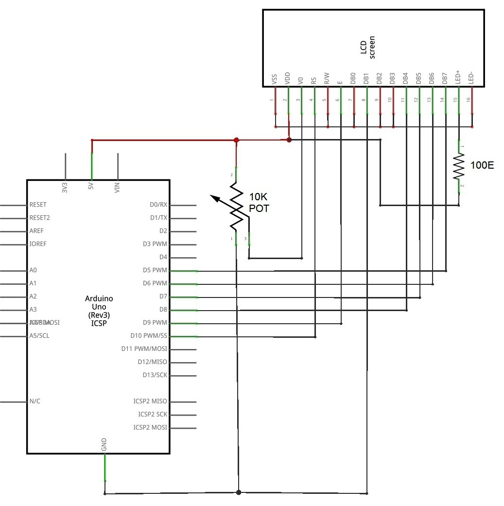
Circuit Diagram
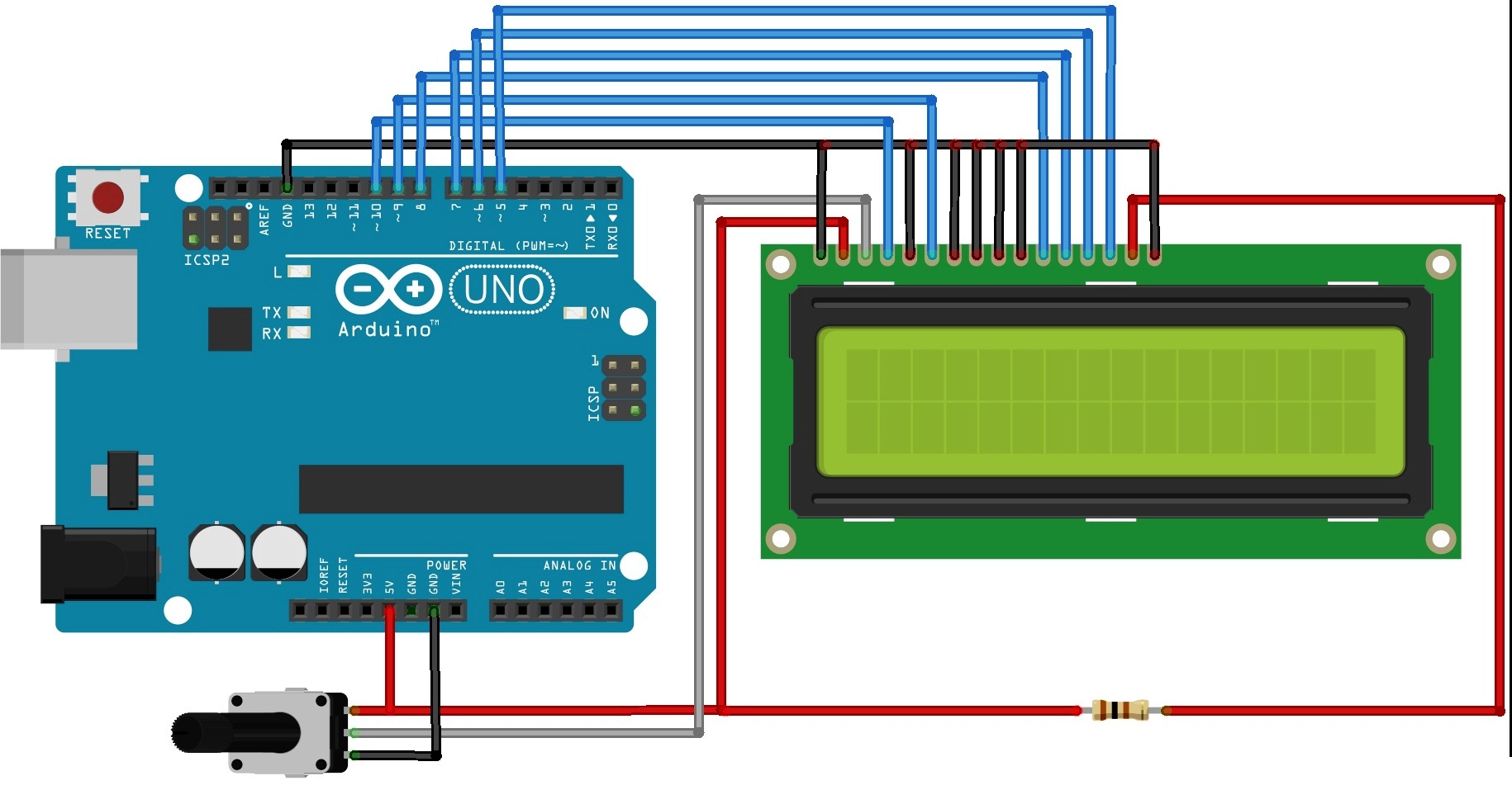
Sketch
#include <LiquidCrystal.h>

// Initialize LCD with following connections
LiquidCrystal lcd(10, 9, 8, 7, 6, 5);

void setup() {
  // Setup LCD Size : Columns, Rows
  lcd.begin(16, 2);
  // Display a message on the LCD.
lcd.print("hello, world!");
}

void loop() {
  // Set position of the cursor to column 0, line 1
  // Note : Counting starts from 0
  lcd.setCursor(0, 1);
  // Displays the number of seconds since reset
  lcd.print(millis()/1000);
}
Output


