

Interfacing Relay with Arduino Uno
Contents
In this tutorial, we are going to interface a 5V Relay module with Arduino Uno to control high power devices. As you might already know, Arduino Uno work on 5V and the maximum current a digital pin can drive is less than 40mA. So technically we cannot drive higher power devices like home appliances DIRECTLY with arduino. That is the need of electromechanical RELAY. In this tutorial we are using a 5V 1 channel relay module as it is a very much popular and most used relay module among enthusiasts. Depends on our use case we can go with 2 channel relay, 4 channel relay, 8 channel relay, etc.
Relay Module
A relay is generally an electrically operated switch. The principle used by the relays is an electromagnet to mechanically operate the switch. So basically it operates a switch using an electromagnet which needs only less power like 5V, 12V or 24V. Different kinds of relays are available in the market like SPDT, DPDT, SPST, 5V, 12V, 24V and with various high current/voltage driving capacity. In this tutorial we are using a 5V relay module.
Pinouts
Let’s dive deep into the 5V relay module which we are using. This module has total 6 pins out of which 3 are used for controlling the relay (low voltage side). While other 3 are the output of the relay (usually high voltage side), where we will connect the device which we want to control.

As shown in the above image :
- NO : Normally Open – This is the normally open terminal of the relay, means if we don’t energise the relay there won’t be any contact with Common terminal. But it will establish electrical contact with Common terminal once the relay is energized.
- C : Common terminal
- NC : Normally Closed – This is the normally closed terminal of the relay, means it will have electrical contact with common terminal whenever the relay is not energised. And there won’t be electrical contact when the relay is energised.
- GND : Ground Pin
- Signal : Actuation signal to control the relay.
- 5V VCC : Operating voltage for the relay.
Working
The principle behind the relay is electromagnetism, a switch operated by an electromagnet. So, a low voltage is enough for an electromagnet to get activated. This small voltage will be given to the relay by Arduino Uno or using some intermediate driver if required.
NO, NC and COM Terminals
Usually SPDT (Singe Pole Double Throw) relays have 3 output terminals, these are the 3 terminals of internal SPDT electromagnetic switch.
Common (COM)
This is the commonly terminal. This terminal will be connected to either of other 2 terminals (NO or NC) based on the state of relay.
Normally Open (NO)
As the name indicates this is normally open terminal, ie. if the relay is not energized (not ON), this pin will be open. We can say that the switch is OFF by default and when the relay is energized it will become ON.
Normally Closed (NC)
As the name indicates it is normally closed terminal, ie. if the relay is not energized (not ON), this pin will be closed. We can say that the switch is ON by default and when the relay is energized it will become OFF.
Interfacing Relay with Arduino Uno
In the first phase of this tutorial we are controlling a normal LED for testing the functionality of the relay as playing directly with AC needs to be very careful.
Components Required
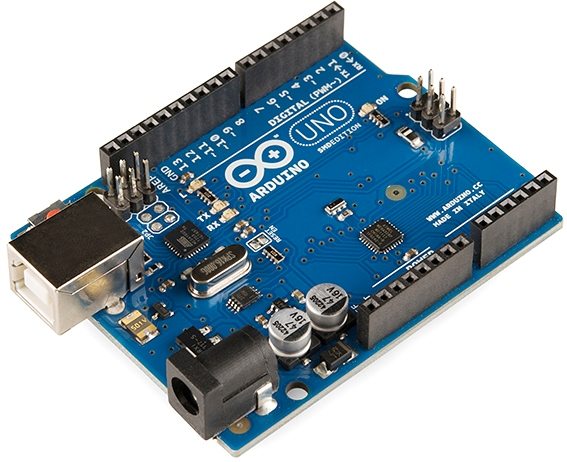
- Arduino Uno
- LED
- 5V Relay Module
- Bread Board
- Jumper Wires
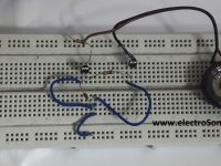
Circuit Diagram

Description
- GND pin of 5V Relay – GND pin of Arduino
- Signal (Input) pin of 5V Relay – pin 7 of Arduino
- VCC pin of 5V Relay – 5V pin of Arduino
- Common pin of 5V Relay – pin 12 of Arduino
- NO pin of 5V Relay – Positive pin of the LED
- GND pin of LED – GND pin of Arduino
Program
int relay_pin = 7;
int led_pin = 12;
void setup()
{
  pinMode(relay_pin,OUTPUT);
  pinMode(led_pin,OUTPUT);
  digitalWrite(led_pin,HIGH);
}
void loop()
{
  digitalWrite(relay_pin,HIGH);
  delay(2000);
  digitalWrite(relay_pin,LOW);
  delay(2000);
}
How to Control AC Mains Devices with 5V Relay?
We can connect our home appliances or other AC mains devices to the output of relay (COM and NO terminals). Please take necessary precautions while playing with AC mains. Make all AC mains connections after switching off the AC power.

Video
Conclusion
Hope that you all are clear with the tutorial. If you want to operate AC devices with relay, make sure you take necessary precautions. If you have any doubts, please let me know in the comment section below.


