

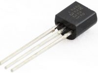
ULN2003 High Voltage and High Current Darlington Transistor Array
The ULN2003 is a monolithic IC consists of seven NPN darlington transistor pairs with high voltage and current capability. It is commonly used for applications such as relay drivers, motor, display drivers, led lamp drivers, logic buffers, line drivers, hammer drivers and other high voltage current applications. It consists of common cathode clamp diodes for each NPN darlington pair which makes this driver IC useful for switching inductive loads.
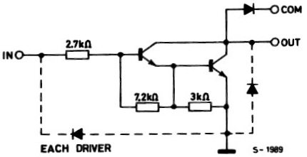
The output of the driver is open collector and the collector current rating of each darlington pair is 500mA. Darlington pairs may be paralleled if higher current is required. The driver IC also consists of a 2.7KΩ base resistor for each darlington pair. Thus each darlington pair can be operated directly with TTL or 5V CMOS devices. This driver IC can be used for high voltage applications up to 50V.
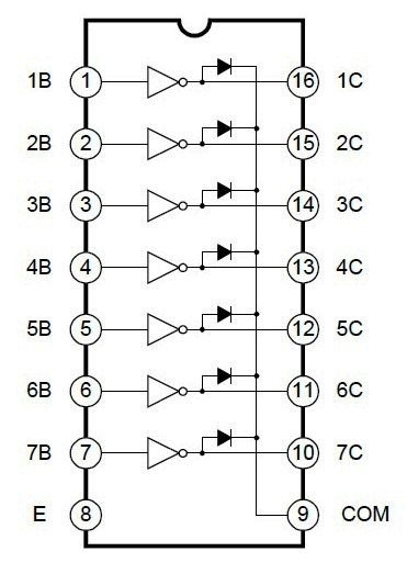
Note that the driver provides open collector output, so it can only sink current, cannot source. Thus when a 5V is given to 1B terminal, 1C terminal will be connected to ground via darlington pair and the maximum current that it can handle is 500A. From the above logic diagram we can see that cathode of protection diodes are shorted to 9th pin called COM. So for driving inductive loads, it must connected to the supply voltage.
ULN2003 is widely used in relay driving and stepper motor driving applications.


can we run relay system without uln 2003 ?
It seems like there is some logic mistake in your experiment. You won’t get any current on the ULN output pins unless there is some load to sink that current.
Hey @Ligo , I’m using rechargeable battery….. but it is able to give 2.5ma…. but I want 10ma….. i used uln2003, but I didn’t get current at 16th pin of uln2003….. help
500mA means, max current driving capacity.
Let me know how did you measure the current.
It will provide only the current required for the load, by following ohms low. I = V/R.
I bought uln2003a circuit from you people, at the time of testing at gave 4 milli amps, i was expecting 500 milli amps, please tell the exact way of getting the exact current . I may have mistaken.
That circuit is not drawn by me.. it is copied from YOUW ANG ELECTRONICS CO.LTD s datasheet.. It may be their mistake… Different manufactures provides different internal diagrams…. I found that most of the datasheets connects diode in the way you pointed… Characteristics of components from different manufacturers are different…. Note : Cut in voltage of every diode is not 0.7V.. it depends… any way I will correct that circuit. .Thank you..
There’s a small mistake in your drawing, the diode at the bottom is shown reversed. If it was as shown, it would clamp the input to 0.7V and the darlinhgton pair could never turn on…
Sue
Yes…… it is better to provide a heat sink..
sir ,all pin can sink 500×8 ma at one time.
Yes of course.. Note that ULN driver can only sink current.. cannot source..
another 1.chip all pin can sink 500ma currents at onetime .help
sir,can i use same 2803 chip to drive 16×64 led matrix and how to connect it (row or column) please help ..