

Interfacing Servo Motor with PIC Microcontroller – MPLAB XC8
Contents

Servo Motor is an ordinary geared dc motor equipped with closed loop servo mechanism which uses position feedback to control exact angular position of the rotor. These are commonly used in robotic arms, legs etc. Servo Motors do not rotate continuously, their rotation is limited to fixed angles. Usually these motors have rotation limit from 90º to 180° and some special have limits 360° or more.
Servo Motors usually have three wires. RED and BLACK wires are used to provide power. Required voltage will depend upon the type of servo you are using, so please refer the specifications given by the manufacture. The third wire is used to provide control signals to control exact angular position of the servo motor. Its color varies for different manufactures such as YELLOW, BROWN, WHITE etc.
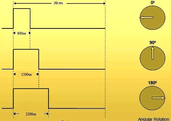
Servo Motor shaft can be moved to desired position by using Pulse Width Modulated (PWM) signals on the control wire.
Unlike DC Motors, reversing the power supply polarity does not reverse the rotation instead of it may damage the control circuitry.
Servo Motors can be easily interfaced with PIC Microcontroller. Here for demonstration we are using PIC 16F877A and VIGOR VS-10A servo motor. The required pulse width of this servo motor ranges from 800μS to 2200μS and rotation angle is greater than or equal to 170°. Its operating voltage range is 4.8V to 6V.
Circuit Diagram
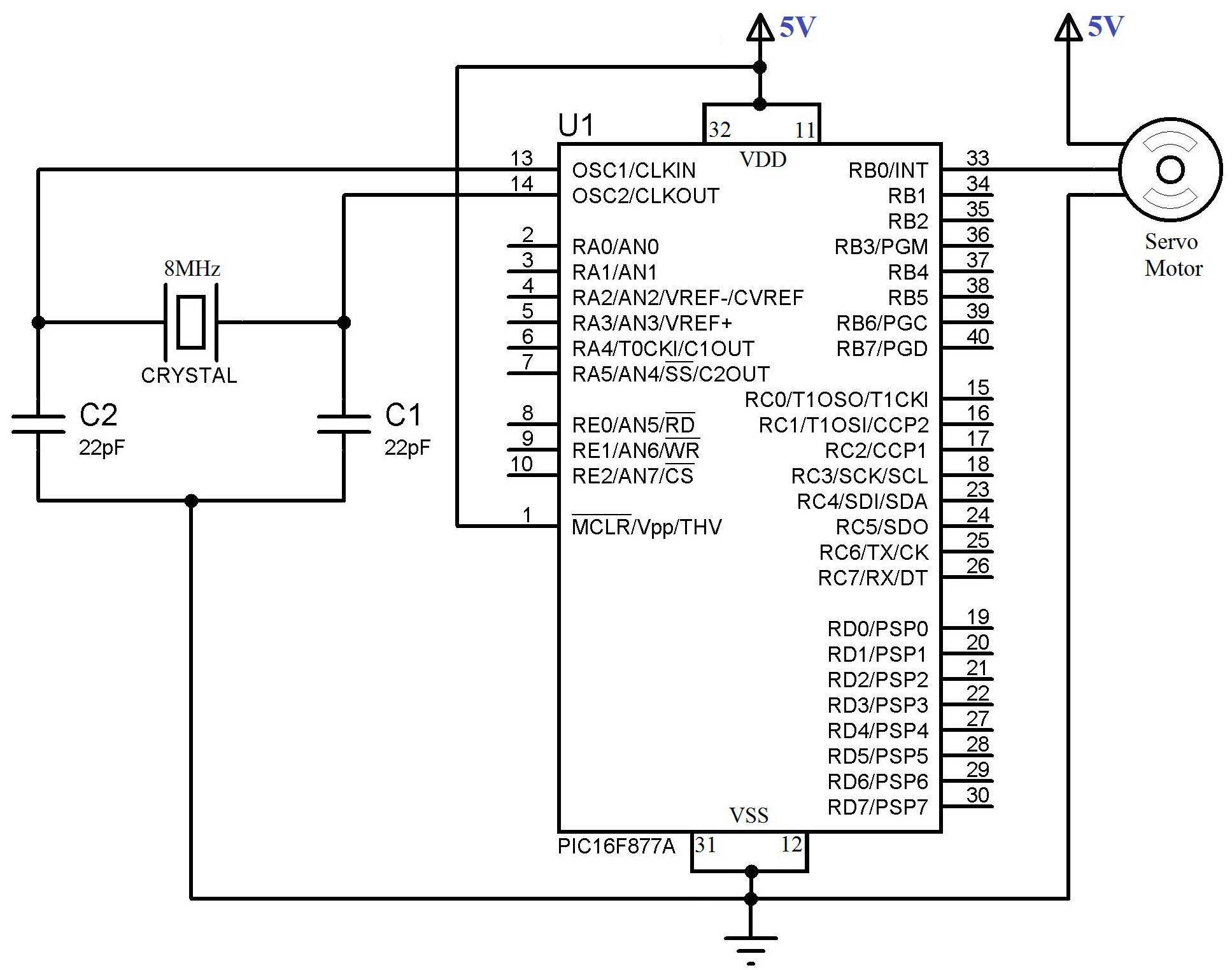
Tip : Use separate power supplies for PIC and Servo Motor OR use proper filtering capacitors otherwise ripples produced by the Servo Motor may affect the working of PIC.
MPLAB XC8 Code
#define _XTAL_FREQ 8000000

#include <xc.h>

// BEGIN CONFIG
#pragma config FOSC = HS
#pragma config WDTE = OFF
#pragma config PWRTE = OFF
#pragma config BOREN = ON
#pragma config LVP = OFF
#pragma config CPD = OFF
#pragma config WRT = OFF
#pragma config CP = OFF
//END CONFIG

void servoRotate0() //0 Degree
{
  unsigned int i;
  for(i=0;i<50;i++)
  {
    RB0 = 1;
    __delay_us(800);
    RB0 = 0;
    __delay_us(19200);
  }
}

void servoRotate90() //90 Degree
{
  unsigned int i;
  for(i=0;i<50;i++)
  {
    RB0 = 1;
    __delay_us(1500);
    RB0 = 0;
    __delay_us(18500);
  }
}

void servoRotate180() //180 Degree
{
  unsigned int i;
  for(i=0;i<50;i++)
  {
    RB0 = 1;
    __delay_us(2200);
    RB0 = 0;
    __delay_us(17800);
  }
}

void main()
{
  TRISB = 0; // PORTB as Ouput Port
  do
  {
    servoRotate0(); //0 Degree
    __delay_ms(2000);
    servoRotate90(); //90 Degree
    __delay_ms(2000);
    servoRotate180(); //180 Degree
  }while(1);
}
Hope you can understand the working of the above program. If you have any doubts just comment below.
Download
You can download the entire project files here.
Servo Motor


sir can i use this for SG90 servo motor
why my program undefined the __delay_us?
insikbradbaek important
Expected PWM. Just surprised at this simple and barbaric approach.
Is ur servo always turning +90° with this code????
how to calculate pulse width? this code is not working for my servo too.
use pulse width according to that servo specifications.
MG996R
how can i drive this servo , pleasee ?? your code dont work with this one..