Basic Electronics

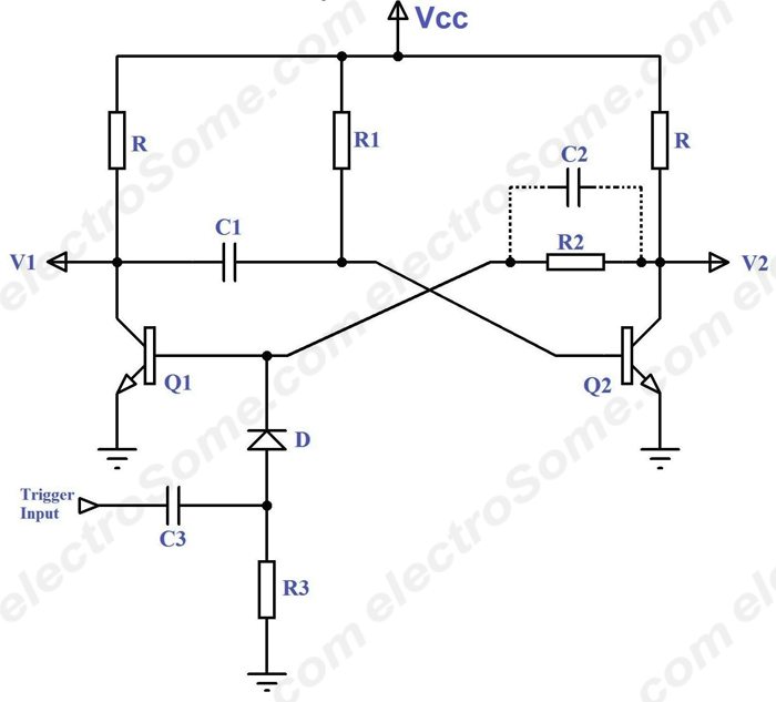
Basic electronics concepts and circuits explained for beginners or students. Circuit diagram and detailed working explanation.

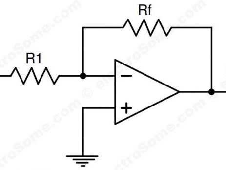
Inverting Amplifier using Opamp

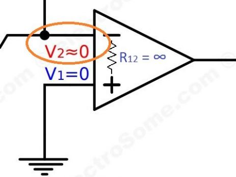
Inverting amplifier is an amplfier whose amplfied output is negatively proportional to the input. Its gain will be negative. For eg. if we provide sine wave input, its amplified output will be 180° out of phase with input. When the input is voltage is increasing, output voltage will decrease and vice versa. Recommended Reading : Opamp - Operational Amplifier We all know that the open loop gain of an operational amplifier is very high for practical applicaitons. So we will apply negative...

Virtual Ground – Opamp

What is Virtual Ground ? As the name indicates it is virtual, not real ground. For some purposes we can consider it as equivalent to ground. In opamps the term virtual ground means that the voltage at that particular node is almost equal to ground voltage (0V). It is not physically connected to ground. This concept is very useful in analysis of opamp circuits and it will make a lot of calculations very simple. Virtual Ground - Opamp Lets see how the virtual...

Opamp – Operational Amplifier

What is an Opamp ? Opamp is the abbreviation of Operational Amplifier. An operational amplifier is a direct coupled high gain amplifier usually consisting of one or more differential amplifiers followed by a level transistor and an output stage. The output stage is generally push-pull or complementary symmetry push-pull amplifier. Opamps are building blocks of analog circuitry and is also known as differential amplifier as its output depends on difference between input signals. It can also be used to amplify both DC as well...

Differential Amplifier using Transistors

As the name indicates Differential Amplifier is a dc-coupled amplifier that amplifies the difference between two input signals. It is the building block of analog integrated circuits and operational amplifiers (op-amp). One of the important feature of differential amplifier is that it tends to reject or nullify the part of input signals which is common to both inputs. This provides very good noise immunity in a lot of applications. Let's see the block diagram of a differential amplifier. Differential Amplifier Vi1 and Vi2 are input...

Monostable Multivibrator using Transistors

Multivibrator is a non linear oscillator or function generator which can generate square, rectangular and pulse waves. Monostable Multivibrator or One-Shot Multivibrator has only one stable state. By default monostable multivibrator will be in its stable state, but when triggered it will switch to unstable state (quasi-stable state) for a time period determined by the RC time constant in the circuit. Monostable Multivibrator using Transistors - Circuit Diagram Monostable Multivibrator using Transistors - Circuit Diagram In the above circuit diagram we can find two transistors which are...

Compensated Attenuator

An attenuator is an electronic device which reduces the power or amplitude of a signal without considerably affecting the wave shape. Thus it works in an opposite way that of an amplifier does. Attenuator provides loss (gain < 1) while an amplifier provides gain (gain > 1). A Compensated Attenuator is a simple two port network which provides a constant attenuation over a wide range of frequencies. Here I am explaining attenuators and compensation in the input of vertical deflection amplifiers used...

Zener Diode Voltage Regulator

Zener Diode is a general purpose diode, which behaves like a normal diode when forward biased. But when it is reverse biased above a certain voltage known as  zener breakdown voltage or zener voltage or avalanche point or zener knee voltage the voltage remains constant for a wide range of current. Clarence Zener is the scientist who discovered this electrical property and the device is named after him. Zener Diode Ordinary diodes will not have any significant current (only leakage current ) when reverse biased below...

Bridge Rectifier

Rectifier A rectifier is a device that converts AC into DC. The power available to us is in the form of AC. But almost all electrical equipments work on DC. So we need a converter   that converts AC into DC. We employ a rectifier circuit for this purpose. Rectifiers are basically classified into Half Wave and Full wave according to the cycles (either Half of a cycle or Full) that are rectified. Among these the bridge rectifier is the most efficient...

>