

Compensated Attenuator
Contents
An attenuator is an electronic device which reduces the power or amplitude of a signal without considerably affecting the wave shape. Thus it works in an opposite way that of an amplifier does. Attenuator provides loss (gain < 1) while an amplifier provides gain (gain > 1).
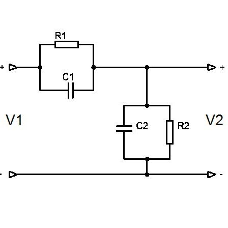
A Compensated Attenuator is a simple two port network which provides a constant attenuation over a wide range of frequencies.
Here I am explaining attenuators and compensation in the input of vertical deflection amplifiers used in oscilloscopes for the sake of explanation.
Uncompensated Attenuator
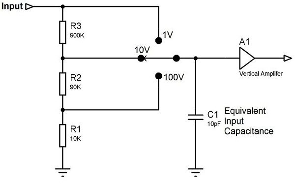
The above circuit shows uncompensated attenuator connected to the input of vertical deflection amplifier. It will provide different attenuations as per the selected input voltage range. The equivalent input capacitance of the amplifier C1 is about 10pF, which includes stray capacitance, parasitic capacitance etc. So we need to account the capacitive reactance of C1 (1/2πFC) while calculating the input impedance of the amplifier. If the input impedance of the amplifier is high for all the frequencies, the attenuation will be relatively constant for all frequencies. But the capacitive reactance of C1 changes with frequency, thus the input impedance of the amplifier also changes. So it will eventually result in different attenuation for different frequencies. At high frequencies capacitive reactance will be very low and the attenuation will be high.
Compensated Attenuator
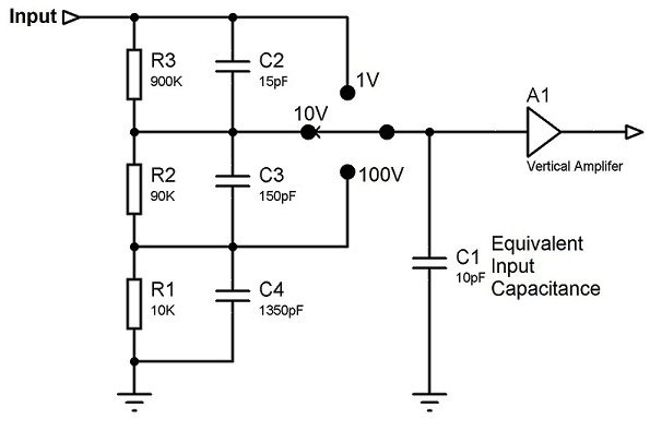
In compensated attenuators we will use capacitive voltage dividers as shown in the above circuit which will improve the high frequency response of the amplifier. Above circuit is a simple compensated attenuator for the sake of explanation but in actual cases more complex compensation networks are used.
Design

