

TransformerLess Low Cost DC Power Supply : Resistive & Capacitive
Contents
One on the major part of our electronics products is the DC Power Supply that converts mains AC voltage to a lower DC voltage. Usually we use a step down transformer to reduce mains AC voltage to desired low voltage AC and then convert it to DC or we use Switched Mode Power Supplies. But in both cases cost is very high and it takes considerable amount of space. Another Low Cost alternative for Transformer and Switcher based power supply is Transformer Less Power Supply. There are basically two types of Transformer Less Power Supplies.
- Capacitive
- Resistive
The main difference between them is, in resistive transformer less power supply excess energy is dropped as heat across a voltage dropping resistor while in capacitor power supplies voltage is dropped across a voltage dropping capacitor so there is no energy loss or heat dissipation.
Capacitive TransformerLess or Capacitor Power Supply

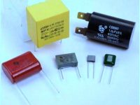
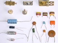
In Capacitor Power Supplies we use a Voltage Dropping Capacitor in series with the phase line. An ordinary capacitor should not be used in these applications because Mains Spikes may create holes in dielectric of ordinary capacitors and the capacitor will fail to work. This may destroy the device by rushing current from the mains. Thus we use X Rated Capacitor with required voltage is used for this task. X Rated Capacitors rated for 250, 400, 600 V AC and higher are available. Reactance of the voltage dropping capacitor should be greater than the load resistance to keep constant current through the load.
Reactance of Capacitor, X = 1/2ΠfC
Where f is the frequency and C is the Capacitance. Thus a 0.22μF capacitor has reactance of 14.4KΩ on mains frequency (50Hz). The approximate value of maximum current can be find out by dividing mains voltage by reactance of the capacitor (since load resistance is small).
I = V/X
I = 230 V / 14. 4 = 15.9 mA
Thus a 0.22μF capacitor can supply a maximum current about 15mA.
Circuit Diagram
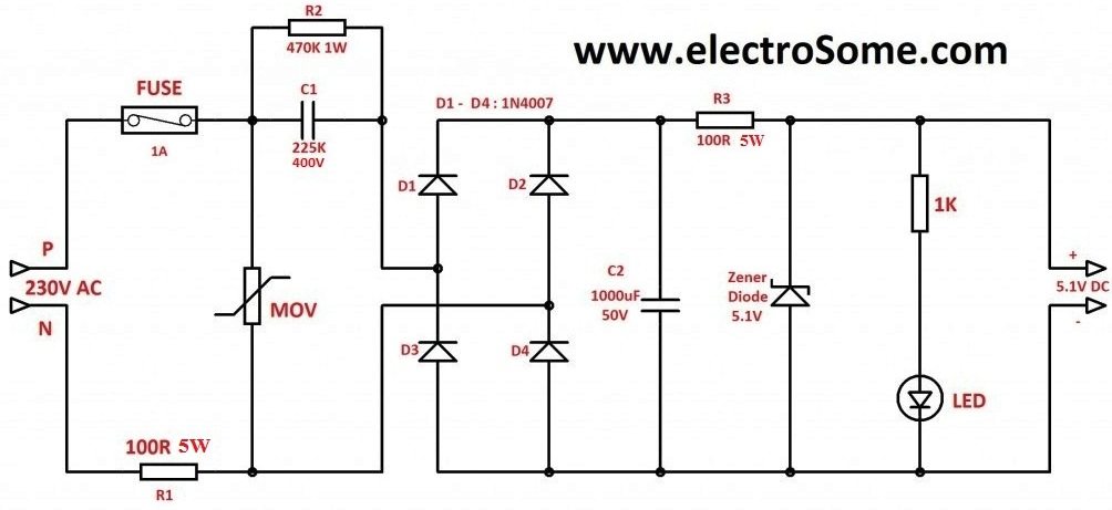
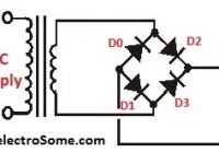
As shown 1A fuse may be used to avoid damages due to short circuit and a MOV (Metal Oxide Varistor) also may be connected as shown above to avoid problems due to voltage transients. The resistor R1 is used to limit the high current that may occur during power on. Capacitor C1 225K (2.2μF) is used as the Voltage Dropping Capacitor. A Bleeder resistor is connected parallel to it for discharging the capacitor when the supply is switched off. Diodes D1 – D4 is wired as Bridge Rectifier and the capacitor C2 is used to filter the pulsating DC. Zener Diode is used to regulate the filtered DC or you can use IC Voltage Regulator for better results. Resistor R3 is used to limit the current through the Zener Diode.
The following table shows the maximum current and open circuit voltage of some commonly used capacitors.
| Capacitor | Voltage | Current |
|---|---|---|
| 104K | 4 | 8 mA |
| 334K | 10 | 22 mA |
| 474K | 12 | 25 mA |
| 684K | 18V | 100 mA |
| 105K | 24V | 40 mA |
| 225K | 24V | 100mA |
Advantages
- Significantly smaller in size and lesser in weight than transformer power supplies.
- Lesser in Cost when compared to Transformer or Switcher based power supplies.
- Capacitor Power Supply is more efficient than Resistive Transformer Less Power Supply.
Disadvantages
- Higher Cost when compared to a Resistive Power Supply.
- No isolation from AC mains which introduces many safety issues.
Resistive TransformerLess Power Supply
Resistive Transformer Less Power Supply is similar to Capacitor Power Supply except that instead of Reactance it uses resistance to limit current. Thus here excess energy is dissipated as heat across the Voltage Dropping Resistor.
Circuit Diagram
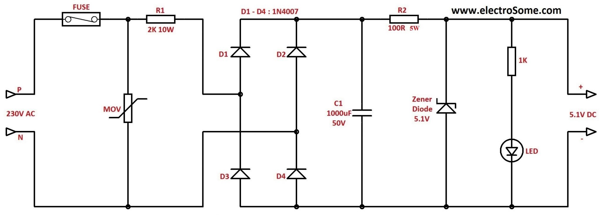
Care should be taken while selecting Voltage Dropping Resistor since the excess power is dissipated across it. Calculate power by multiplying Voltage and Current. P = VI
It is better to use a resistor of double the rated power.
Advantages
- Significantly small size and less weight than transformer based power supplies.
- Lesser Cost than Transformer or Switcher based power supplies.
- Lesser Cost than Capacitor Power Supply.
Disadvantages
- No isolation from AC Mains which introduces many safety issues.
- Resistive Power supplies are less efficient as the excess energy is losted in the form of heat across the Voltage Dropping Resistor.
Caution
Don’t Try this circuit if you don’t have much experience with electronics. Care should be taken while testing or using this circuit. Don’t touch at any points of the circuit since some points of this circuit is at Mains Potential. After constructing and testing enclose the circuit in a metal casing without touching PCB and metal-case. The metal case should be properly earthed to avoid shock hazards.


Could you please assist with a 230v 15 amps to a 60v 57 amps transformer less circuit or its components
I don’t understan how the (maximum?) open circuit voltage figure is obtained. For example, for 225K, it’s 24V
100mA. I undersntan how we get 100mA (although in theory it should be 158mA, isn’t it? but in reality it might be 100mA). But what is the limiting factor for the voltage?
can we use 2 zener and 2 normal diodes instead of 4 normal diodes in bridge circuit
Sir , What if I want to increase the current upto 18 apms?
MOV is for spike protection. You may use 275V MOV.
You can use for 8051 microcontroller with proper filters.
What is mov and what should be its value.
Can i use this with my 8051 microcontroler with rtc.
Check this : https://electrosome.com/automatic-night-lamp/
hi Ligo George
are you make and test this circuit?
I don’t think it will be easy to achieve. You need very big capacitors for that. Better go for a SMPS power supply.
Hi, I want 12volt 5watt load , how to calculate this curcite.
Sorry, presently I don’t have.
have someone circuit schematic?
do you have someone circuit?
It will be possible, but you need to do some R & D on it.
i need a transformerless: 6V at 120VAC and 12V at 220VAC! Is possible?
How can I get 60V DC 300ma on output?
It will work only with AC.
Is it possible to get 130mA by this circuit, What Will Happen If i give 230V DC as input to this circuit?
Is it possible to get 130mA by this circuit, What Will Happen If i give 230V DC as input to this circuit?
ok, Thanks for your reply
The size of capacitor increases as per your current requirement. I haven’t yet used smd component for this.
Hello Ligo i am waiting
hello Liho,
i am waiting for your answer, please suggest as soon possible from your side.
ok i will do that and what about the SMD component?, Can i use it? special for capacitors, as u recommended X rated capacitor.
Try increasing the resistance values.
Thank you Ligo George…,
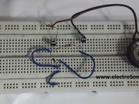
I have done this project, getting sufficient voltage, but it is not 5V DC, its 12V DC so by using 7805 i achieved 5V DC.
Only one problem i have that is of heating from the resisters of 100R 5W, both resister got heated very high.
Any solution of this overheating of resistor?
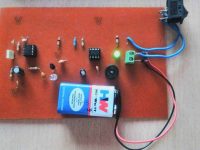
i have also attached an images of supply and marked that two resistors.
And one another question is that can i use SMD components for the same value?
Hi,
How do i know output voltage of x-rated capacitor. I need a supply of 5v, 40-50mA. Using 105K will give me 40mA but output voltage will be 24V, and i will have to drop rest of it across a resistance which will cause power wastage. How do i find out X rated cap with output voltage suitable to my application.
It is a class of non polar capacitors… https://electrosome.com/x-and-y-rated-capacitors/
It will be available in all local electronics shops….
Just tell the value of capacitor instead of “X Rated” ..
Hai Ligo George
I am unable to understand the X rated capacitor…?
what is X-rated capacitor…
Where do I get it…
is it available in the online shoping like Digi key…
Can u pls mention any online portal where I can buy X-rated capacitor…..
is there any industrial name for X-rated capacitors….like disk capacitor.,Electrolytic,Ceramic Capacitors,Polyester – Box Capcitors, Polyester – Myler Capacitors
which capacitor should I buy……
I stay in india….
Yes, you can use multiple x rated capacitors…
You may also use other regulators like 7805 etc.
What stops one from using multiple x rated capacitors to generate a higher current? Are there issues with heat in other parts of the circuit across resistors that make it impractical for higher current applications? Could the output be regulated properly instead of with a zener?
I don’t think you can get 40A with this.
hello all,what if i want a high current battery charger of say 40A. What modifications can be done
Eg : MOV 10D471
what is the MOV item number? i mean how can i ask from the shop?if we take capacitor,it has a number like 10uf 16v.then how can i ask MOV?
Current passing through R1 and R3 is independent of load current. It is determined by majorly by C1 in capacitive, or by R1 in resistive. The load current only affects the current passing through the zener diode that takes up whatever left over from the LED and the load.
The current that a transformerless power supply can supply is determined by design by changing the values of components. Once the appropriate values are decided, the supplied current stays the same regardless of load. Simply speaking, in the capacitive circuit, roughly 150mA will flow through R1 and R3 once plug in.
In fact, R3, and R2 in resistive circuit are redundant. They are necessary only in transformer power supply to limit the current passing through the zener diode as theorectically the transformer power supply can suppy an infinite amount of current without load.
I’ve just provided some information to hossein above. You may want to read those.
Transformerless power supply is designed for a specific application that consume small current from a few mA to a few tenths mA. Current capacity is pre-determined by either the dropping C1 in capacitive or R1 in resistive. The available current capacity will distribute among the zener diode, LED and the load.
Some of the power ratings of components in both capacitive and resistive circuits are too low.
In the capacitive circuit, C1 is labelled 225k 400V; 225k means 2,200,000 picofarad or 2.2 microfarad. That means current available is roughly 150mA.
Power dissipated by R1 = I^2 * R = 2.25W. If 1W rating as indicated is used, it certainly will blow in a minute. Use 5W will be safe.
The same is true for R3. In a transformer power supply, R3 is needed to limit the current flowing through the zener diode. In these two circuits, the current has been limited already, R3 is not necessary. Otherwise, maximum power dissipated by R3 is close to that of R1. Then a 5W rating resistor should be used as well. My suggestion is to get rid of R3.
As for the zener diode, there is no power rating for it. Suppose no load is connected, about 5mA will pass through the LED, the remainder around 145mA will flow through the zener that would dissipate a power of VI = (5.1)(145mA) =0.74W. Most zener diodes are rated 1/4W to 1W. Higher ratings is a bit hard to find and probably more expensive. Use a 1W rating should be fine.
In a custom-designed circuit, the load current is known, so all the components can be adjusted to provide the required load current, and low rating components like 1/8W to 1/2W could be used.
The resistive circuit supplies 110mA current. Power of R1 = I^2 * R = 24.2W. You decide the proper rating of R1 yourself. As mentioned, both circuits are for supplied current ranging from a few mA to a few tenths mA. For example, if supplied current is 23mA, R1 will be 10k ohms, then power dissipated by R1 is 1W only.
R2 is redundant, if you want it to stay in the circuit, use a 2W rating.
For the zener diode, P = VI = 5.1 * 0.11 = 0.561W. If you can’t find a 1W zener, use a 0.5W one, and make sure the load is connected before plug-in to mains.
MOV stands for metal oxide varistor which is a voltage sensitive element that will shunt current to protect the circuit when line voltage surge above the rated voltage.
Can i use a ceiling-fan capacitor (Metal film) of same rating instead of x-rated capacitor??
Can I use x-rated capacitor in ceiling-fan??
hi
please can help me.
whats Mov in circuit diagrams???
and when i use first diagram R1 resistor warm up and Burned after 10 Seconds
what should i do??
Thanx! I got it to work. It dropped a great deal of the output voltage but this micro also works at lower supply voltages.
I don’t understand your question?? What limit??
the answer to the first part of the question is very handy but you still haven’t said why it is restricted to voltage. thanks
Maximum output voltage will be the maximum input mains voltage..
I find this interesting but I still have a question. What is the maximum voltage from a transformerless circuit and why is it limited to the voltage?
Read the application note of Microchip :
http://ww1.microchip.com/downloads/en/appnotes/00954a.pdf
If so..Increase the wattage.. It will depend on the current consumption of your load..
Hey, nice work! Here is my question. My circuit has a micro (PIC16F505), a BTA06-600CW Triac and a few other components. I need this PS to supply at least 40mA. What’s your suggestion? My plan is to use the micro to switch my Triac.
Should I use 3w or 5w resistors for R1 and R3? Both R1 and R3 with 1W are getting burnout, they are too hot …
Are these values ok to AC 110V?
No .. never
I want to use 230 vac to 12v dc
Sir is it better than transformer or SMPS ?
Increase the wattage of the resistor…
or use two 220 ohm resistors in parallel..
Bro the R1 resistor is getting Burnout , so instead of 100ohms can i use 2nos of 100ohms in parallel
is it a correct procedure…..
In my opinion ..Transformer less power supplies are not suitable for variable applications.. It is better to use transformer… or make a variable smps power supply..
how can we make variable
Resistive TransformerLess Power Supply maximum output voltage 20volts??/
R2 in the resistive power supply is not needed. It serves NO purpose.
mah,……. ??…. Ah is the rating of battery,,…. for producing 1.5A it is better to use transformer power supply… transformer less power supplies are suitable only for producing low currents..
is this circuit can produce 1500 mah? what capacitor should i used.. please help thanks in advance
for 1500 ah what capacitor should i use?
For 3A, use a transformer power supply,…….. transformer less power supply is not suitable for high current applications………
Thank you for pointing some of the errors.
what kind of capacitor to be used for the output of 3000ma of current ? thanks for this circuit..
There is no 10K resistors..
It is an X – Rated capacitor …….
The 10k resistor on the front-end will dissipate more than 5 watts.
How can a 225 capacitor be 1w????
R1 is used to limit inrush current during startup leave it 100 ohms……..
R2 is used to discharge the capacitor to avoid the risk of electric shock…
The table shows the open circuit voltage and maximum current can drawn by using some capacitors…
1. What do you mean by “table shows the maximum current and open circuit voltage of some commonly used capacitors”??
Did you mean the design value for the circuit above or what?
2. how to calculate the value of R2 and R1?