

Astable Multivibrator using Transistors
Contents
An Astable Multivibrator or a Free Running Multivibrator is the multivibrator which has no stable states. Its output oscillates continuously between its two unstable states without the aid of external triggering. The time period of each states are determined by Resistor Capacitor ( RC ) time constant.
Astable Multivibrator using Transistors – Circuit

In the above diagram we can find two transistors which is wired as a switch. Please do read the article Transistor as A Switch. When a transistor is ON, its collector and emitter act as a short circuit. But when it is OFF they acts as open circuit. So in the above circuit when a transistor is in OFF state its collector will have the voltage Vcc and when it is ON its collector will be grounded. When one transistor is ON the other will be OFF. The OFF time of transistor is determined by RC time constant.
When the circuit is switched on, one of the transistor will be more conducting than the other due imbalance in the circuit or difference in the parameters of the transistor. Gradually the more conducting transistor will be driven to Saturation and the less conducting transistor will be driven to Cutoff.
Working
- When the circuit is switched on one transistor will driven to saturation (ON) and other will driven to cutoff (OFF). Consider Q1 is ON and Q2 is OFF.
- During this time Capacitor C2 is charging to Vcc through resistor R.
- Q2 is OFF due to the -ive voltage from the discharging capacitor C1 which is charged during the previous cycle. So the OFF time of Q2 is determined by R1C1 time constant.

- After a time period determined by R1C1 time constant the capacitor C1 discharges completely and starts charging in reverse direction through R1.
- When the Capacitor C1 charges to a voltage sufficient provide base emitter voltage of 0.7V to the transistor Q2, it turns ON and capacitor C2 starts dischargeing.
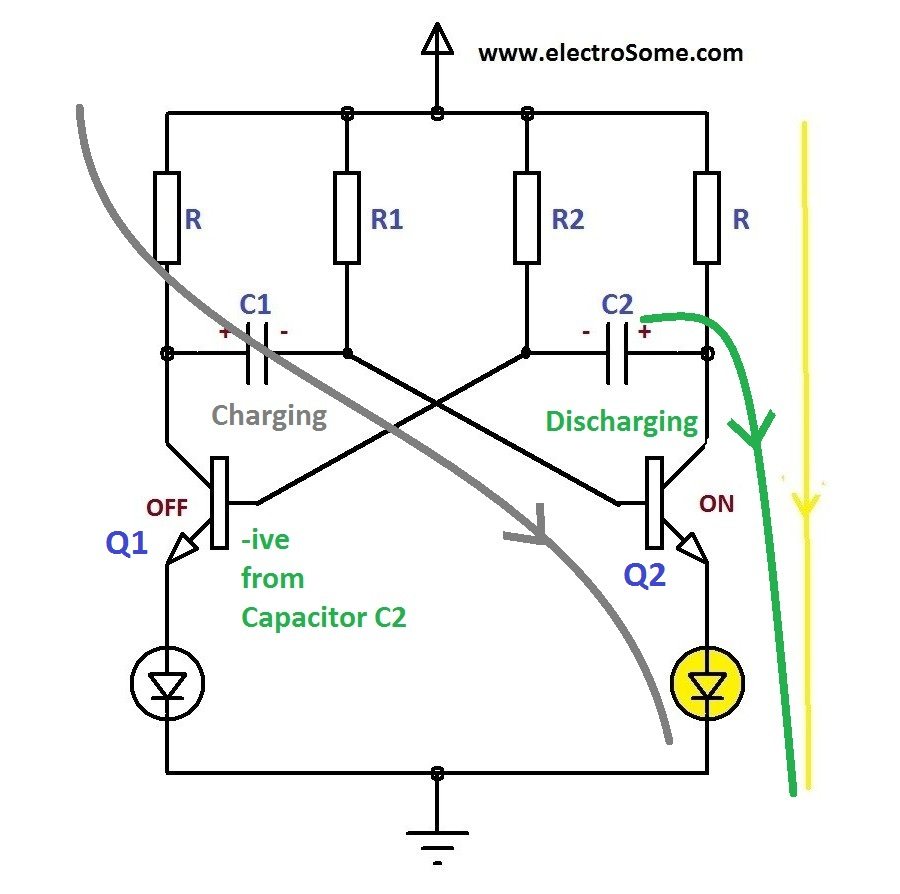
- The negative voltage from the capacitor C2 turns off the transistor Q1 and the capacitor C1 starts charging from Vcc through resistor R and base emitter of transistor Q2. Thus the transistor Q2 remains in ON state.
- As in the previous state, when the capacitor C2 discharges completely it starts charging towards opposite direction through R2.
- When the voltage across the capacitor C2 is sufficient to turn ON transistor Q1, Q1 will turn ON and capacitor C1 starts discharging.
- This process continuous and produces rectangular waves at the collector of each transistors.
- Note : Charging time is very less compared to discharging time.
Design
R – Collector Resistor
The resistance R should be designed to limit the collector current Ic with in a safe limit.
R = V/Ic , where V is the voltage across the resistor R.
In normal cases, V = (Vcc – Vce) = (Vce – 0.3) but when an emitter load like LED is connected,
V = (Vcc – Vce – Vled) , where Vled is the voltage drop across LED.
Usually the maximum collector current Ic will be much higher than than the current required for emitter load such as LED. In these cases Ic should be chosen in such a way that it should not exceed the max current limit of emitter load.
So,
- R = (Vcc – Vce – Vload) / Ic
R1 & R2 – Base Resistors
R1 & R2 should be chosen such that it should give the required collector current during saturation state.
- Min. Base Current, Ibmin = Ic / β, where β is the hFE of the transistor
- Safe Base Current,Ib = 10x Ibmin= 3 x Ic / β
- R1, R2 = (Vcc – Vbe) / Ib
T1 & T2 – Time Period
- T2 = OFF Period of transistor Q1 = ON Period of Transistor Q2 = 0.693R2C2
- T1 = OFF Period of transistor Q2 = ON Period of Transistor Q1 = 0.693R1C1
From these equations we can find the value of C1 and C2.
Duty Cycle
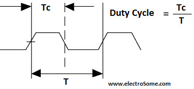
It is the ratio of time Tc during which the output is high to total time period T of the cycle.
Thus here, Duty Cycle = Toff/(Toff + Ton) when the output is taken from the collector of the transistor T.
Calculator
Making Edges Sharp
Due to the initial capacitor charging current, LOW -> HIGH edge of output is not sharp. If you need sharp edges you can use 2 additional resistors and diodes.
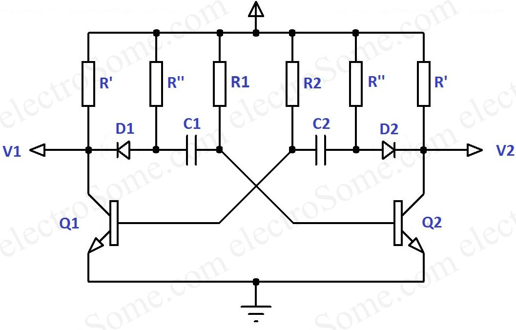
The diodes D1, D2 will prevent charging of capacitor through collector resistor R’. Thus capacitors C1, C2 will charge through R”, makes the output waves sharp.


Discharging is done via R1 and R2. Keep in mind to use electron and not hole flow.
what is the values of resistors in Making Edges Sharp circuit
please take the topic on Astable and Monostable Blocking oscillators
decent. Though you should also explain why the initial conditions have been set as thus.a switch turning on because of differences is ok.However how one of the caps is pre-charged to Vcc is important to understand.
For ON transistor base also connected to -ve plate of capacitor then how it is on
the OFF time of Q2 is determined by R1C1 time constant.( how it is true then)
u r saying that charging through collector resistor
Thanks a lot for the feedback.
It depends on the transistor you are using. Check the datasheet of transistor for me details.
Thanks for this u helped me to score 10marks in my exam thanks a lott
Hi may i know what is the maximum frequency it can achieve?
Is there any maximum frequency limitation?
Thanks for the feedback 🙂
Upon my word, i’ve never seen such good explanations as the ones you give here. Thank you for sharing.
PS: Sorry for my english.
Value of R1, R2 is high compared the collector resistor R”. So it will charge through collector resistor R only.
Great Explanation!!
But i’ve seen other videos saying that the capacitor C1 will charge through resistance R1 when Q1 is ON and i’m so confused about this ,Can you explain ?
LOW to HIGH transition means, it is an impulse (or ac with very high frequency). For this capacitor acts like a short circuit or it consumes good current during that transition. So that loading effect will come on output voltage.
You mean the power supply of this circuit ?
Any component is getting heated ?
Can you please elaborate the reason why we are not getting a sharp edge in the first case ??
ya i done …. i have one problem , i have designed a proper PCB for this circuit and soldered and it is a circuit for RF…. but i have a problem … initially i connected multi-meter to power supply and fixed it to 4 volt then i connected this 4 volt to my circuit then suddenly multi-meter is showing 1.2 volt… i m not getting why it is happening ….. is it the problem with impedance mismatch ??… if you have any idea then please help me
Just calculate it using the equations or use the above calculator for that.
Good Question.
It is the discharging time matters.. not charging time.
hello….. please provide me the value of R and C for 500KHz and 1MHz frequency.
sir,
these two capacitor are charging through resistor R but its frequency depend upon resistor R1 , R2 why and how it happen? I have a Buzzer circuit using Astable multivibrator…pls explain.
Thanks for the compliment.
it works!!!!!
You mean to make sharp edges ?
dear sir ,
how design the astable multivibrator with round off noise remover
There is no chance for both sides to be in proper balance. Each resistors will have slight difference in their values and each transistors will have changes in beta, base resistance etc.
The best way is to use a small microcontroller.. otherwise the circuit will become very complex.
why cant both the transistors Q1 and Q2 be in the ON stage coincidentally?
How can I design a circuit for 3 traffic lights
Note:
Voltage source 12 battery
12 relays
Time
59s red
3s orange
59s green
Hello,
Sorry, the above article is about transistors. If you want more support please use our forums, http://electrosome.com/forums
Can Anyone.. Design Astable multivibrator using OP-AMP to generate a square wave of 5 KHz with 70% duty cycle ?
Thanks for the feedback… 🙂
Well explained and easily comprehensible. Especially the graphical illustration of the working should be appreciated. Thanks a lot!