

Simple Water Level Indicator
We have already posted about a Water Level Indicator and Controller using PIC Microcontroller. Today I am presenting a very useful, very cheap and very simple circuit using transistors for beginners in the field of electronics. This simple circuit can indicate the level of water in your tank using LEDs.
Circuit Diagram
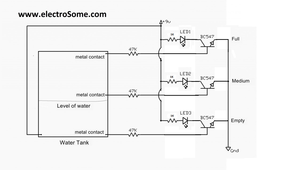
The connections and arrangements are made as shown in the figure above. The +9V is supplied to water using a metal contact. In this circuit all the transistors are working as a switch. When the water touches the metal contact in which base of each transistor is connected, a small current flows and turns on the transistor. When a transistor turns on, LED connected to it glows. Thus LEDs will be turned on depending up on the level of water. By using a relay we can also control the level of water.


Stainless steel is a poor conductor of electricity.
use stainless steel screws as terminals ,wont gets corroded ever.
Check new wireless water level indicator
Sorry, I don’t understand your question. Please elaborate.
what type of sensor can we use to vary current
You can use the following.
1. AC Sensing
2. Reduce current
3. Use float sensors
I read that ionization leads to deposits on the terminals inserted in water. This means you have to clean the terminals frequently. How to avoid this?
You can reduce or increase the value of base resistor depending upon the required sensitivity.
Is possible no to use the 47k resistor on the base?. What would happen?
It is a simple water level indicator. You need additional components to add relay.
how can we connect a relay to this circuit
Yes, there will be corrosion..
1. AC voltage sensing avoids corrosion.
2. You may use Float or Tilt sensor to avoid corrosion
3. Reduce sensing current to reduce corrosion
What about corrosion. Here in Mira Bhayandar we quite frequently use Creek Water or Well/”Boring” water along with Tap (Sweet) water. If we use copper wire there may be corrosion. Is there a solution for this problem.
No, Positive of the 9V battery is connected to the water..
Sir, Is the negative of the 9V source connected to the lower part of the water tank. Im not understanding. Plz reply.
You should use more components for that.. it will loss the simplicity of above circuit.
Take that leds as for indicating water level. instead of assign an led as EMPTY.
is there a way to shut off the empty light when the water is in full level ? pls help me sir . thanks 🙂
what types of wires shoul i use ?
reduce the 1K to 680 ohm.
hi if i use a 5 volt power supply what changes i need to make?
http://www.electrosome.com/water-level-indicator-controller-pic/
can u please help me if i want to implement motor to fill my tank if the taank comes to empty portion…
The circuit will not work with 4.7k resistors in the collectors. The correct way to write values is 4k7 so the decimal point is not needed. The correct value is 470R.
You should have a current-limiting resistor in series with each LED
led takes very low power from the source…a single battary can work minimum one month
when the tank is full three led are on and the battery will empty