DC Motor Driving using H Bridge
Contents
H Bridge is a simple electronic circuit which enables us to apply voltage to load in either direction. It is commonly used in robotics application to control DC Motors. By using H Bridge we can run DC Motor in clockwise or anticlockwise directions. This circuit is also used to produce alternating waveforms in inverters.
Basic H Bridge
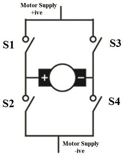
When switches S1 and S4 are switched on, motor runs in clockwise direction.
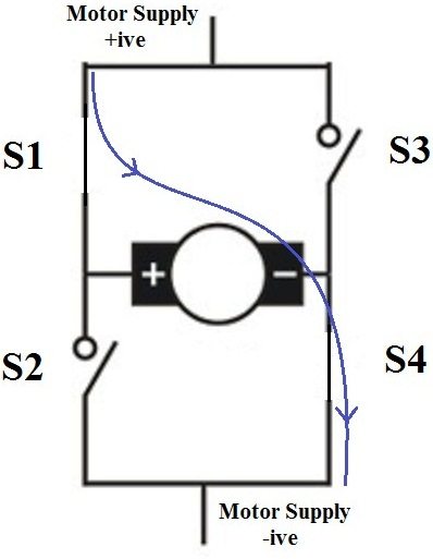
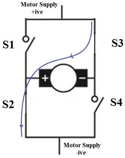
When S2 and S3 are switched on, motor runs in anticlockwise direction.
In actual practice these switches are replaced by transistors. Nowadays H Bridge ICs such as L293D and L293 are available.
Transistorized H Bridge
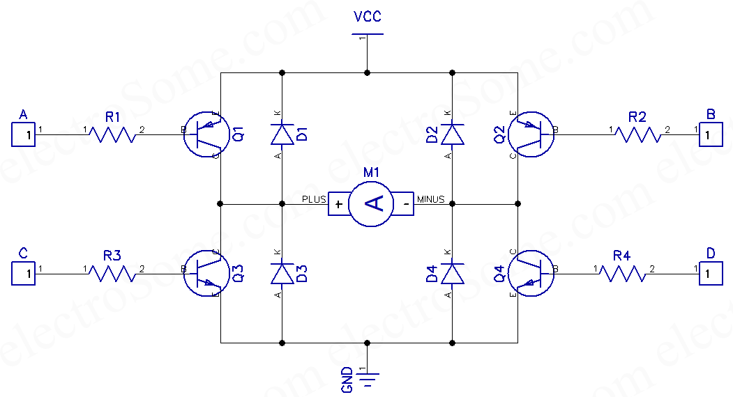
In this circuit all transistors are wired as switches. An NPN transistor (Q3 and Q4) will be ON when we give HIGH to it and a PNP transistor (Q1 and Q2) will be ON when we give LOW to it. So when (A = LOW, B = HIGH, C = LOW, D = HIGH), transistors Q1 & Q4 will be ON and Q2 & Q3 will be OFF, so the motor rotates in clockwise direction. Similarly when (A = HIGH, B = LOW, C = HIGH, D = LOW), transistors Q2 & Q3 will be ON and transistor Q1 & Q4 will be OFF, thus the motor rotates in anticlockwise direction. 1N4148 (D1 ~ D4) is uses as freewheeling diode as it is a fast switching diode. It avoids problems due to negative voltage produced by the back emf the dc motor. Resistors R1 – R4 are used to limit the input current of transistors and are designed in such a way that transistor will work as a switch. Transistor should be chosen according to the current requirements of the DC Motor.
Design of Input Resistors
- IL = Max. Motor Current
- Ib = IL/β, Minimum input current required to flow current IL through the load (active region).
- Ib’ = 10xIb, To make sure that transistor works in saturation region.
- Rin = (Vin – Vbe)/Ib’
- Take Vbe = 0.7V
This circuit is also used in inverters for producing alternate current across the load. In Square wave inverters, square wave is applied to inputs A, B and in sine wave inverters Pulse Width Modulated (PWM) square wave is applied to inputs A, B. Freewheeling diodes D1 – D4 can be avoided for resistive loads.