

L293D – Quadruple Half H DC Motor Driver
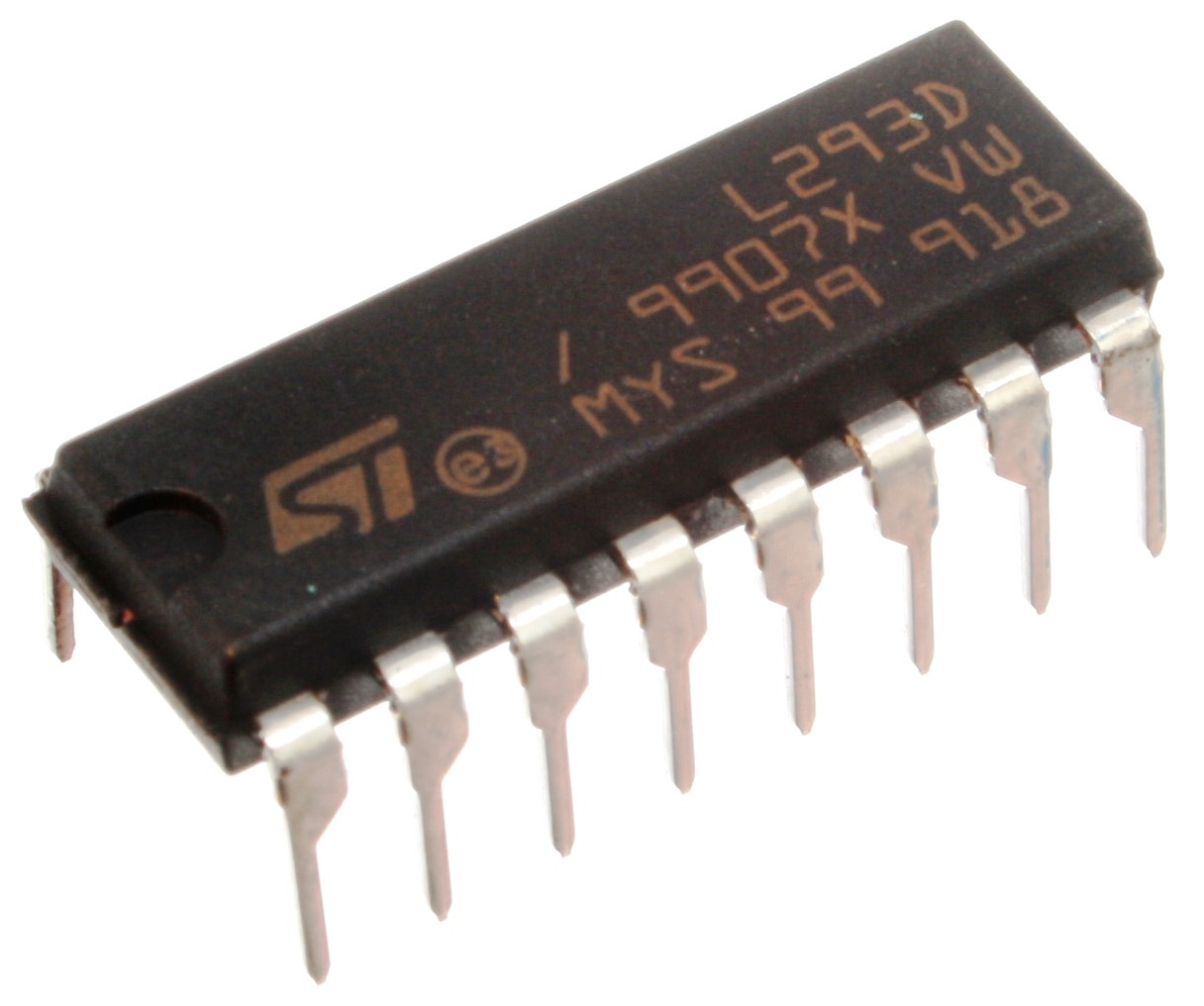
L293 and L293D are quadruple half H Bridge driver having high current capability. It can also be seen as a dual H Bridge driver for driving Motors. L293D can provide currents up to 600mA and L293 can provide currents up to 1A at voltages ranging from 4.5 to 36. Both L293 and L293D are designed to drive inductive loads such as solenoids, relays, dc motors, bipolar stepper motors and other high current or voltage applications.
Features
- Wide range of supply voltage from 4.5 to 36v
- Separate Input Logic Supply can be provided
- Output Current per channel 1A for L293 and 600mA for L293D
- Peak Current per channel 2A for L293 and 1.2A for L293D
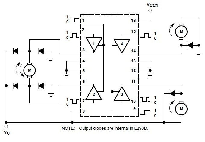
- Output Clamp diodes are provided to drive inductive loads in L293D.
- Automatic Thermal Shutdown
Pin Diagram
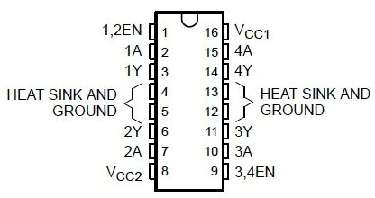
- Vcc1 : Logic Input Voltage
- Vcc2: Driver/Motor Supply
- A : Input
- Y : Output
- 1, 2 EN : Enable Of First Pair 1, 2
- 3, 4 EN : Enable of Second Pair 3, 4
Drivers are enabled in pairs. Logic HIGH at EN1,2 pin enables the drivers 1 and 2. Logic HIGH at EN 3,4 enables the drivers 3 and 4. Logic Voltage should be provided to the Vcc1 pin and motor supply is given to Vcc2 pin. For example, if your motor works at 12v and you are going to control it with control signals from a PIC Microcontroller. Then you have to connect 12V to Vcc2 and 5V to Vcc1 pin and the ground of both supplies should be common.
For more details please read the datasheet and you can download it here…

