

Interfacing Rain Sensor with Arduino
Contents
In this article we are going to explain about interfacing Rain Sensor with Arduino. The rain sensor module is an easy tool for rain detection. It operates as a switch when raindrop falls through the raining board and also it measures rainfall intensity. The module features, a rain sensing board and the control board that is separate for more convenience, power indicator LED and an adjustable sensitivity though a potentiometer.
Rain Sensor Module
Raindrop sensor is basically a board on which nickel is coated in the form of lines. It works on the principal of resistance.
Rain Sensor module allows to measure moisture via analog output pins and it provides a digital output when a threshold of moisture exceeds.
The module is based on the LM393 op amp. It includes the electronics module and a printed circuit board that “collects” the rain drops. As rain drops are collected on the circuit board, they create paths of parallel resistance that are measured via the op amp.
The sensor is a resistive dipole that shows less resistance when wet and more resistance when dry. When there is no rain drop on board it increases the Resistance so we gets high voltage according to V=IR.
When rain drop present it reduces the resistance because water is a conductor of electricity and presence of water connects nickel lines in parallel so reduces resistance and reduces voltage drop across it.
Specifications
- Adopts high quality of RF-04 double sided material.
- Area: 5cm x 4cm nickel plate on side,
- Anti-oxidation, anti-conductivity, with long use time;
- Comparator output signal clean waveform is good, driving ability, over 15mA;
- Potentiometer adjust the sensitivity;
- Working voltage 5V;
- Output format: Digital switching output (0 and 1) and analog voltage output AO;
- With bolt holes for easy installation;
- Small board PCB size: 3.2cm x 1.4cm;
- Uses a wide voltage LM393 comparator

PinOut

| Pin | Description |
|---|---|
| Vcc | +5 Volts Power Source |
| GND | Ground or negative power source |
| D0 | Digital Output. Goes low when moisture exceeds set threshold. |
| A0 | Analog Output – Zero to five volts. The lower the voltage, the greater the moisture |
| POWER LED | Indicates that power is applied |
| OUTPUT LED | Illuminates when moisture has exceeded threshold set by sensitivity adjustment. |
| Sensitivity Adjustment | Clockwise is more sensitive. Counterclockwise is less sensitive. |
Connecting with Arduino

Source Code
Arduino Code
const int sensorMin = 0;
const int sensorMax = 1024;
void setup()
{
  Serial.begin(9600);
}

void loop()
{
  int sensorReading = analogRead(A0);
  int range = map(sensorReading, sensorMin, sensorMax, 0, 3);

  switch (range)
    {
      case 0:
        Serial.println("RAINING");
        break;

      case 1:
        Serial.println("RAIN WARNING");
        break;

      case 2:
        Serial.println("NOT RAINING");
        break;
    }
  delay(1000);
}
Code Explanation
Initialize the lowest and highest sensor readings with type as an integer and variable name.
const int sensorMin = 0; // sensor minimum
const int sensorMax = 1024; // sensor maximum
The setup() routine runs once when we reset it or power the board. Here we are initializing serial communication at 9600 baud rate.
void setup()
{
  Serial.begin(9600);
}
The loop function runs over and over again forever. Firstly this code reads the analog signal at A0 pin from Rain sensor and maps those measured value with initialized values.
void loop()
{
  int sensorReading = analogRead(A0);
  int range = map(sensorReading, sensorMin, sensorMax, 0, 3);
Checks the measured value with pre-stored condition and displays the weather condition like RAINING, RAIN WARNING & NOT RAINING.
  switch (range)
  {
    case 0: // Sensor getting completely wet
      Serial.println("RAINING");
      break;
    case 1: // Sensor getting partially wet
      Serial.println("RAIN WARNING");
      break;

    case 2: // Sensor dry
      Serial.println("NOT RAINING");
      break;
  }
  delay(1000);
}
Working
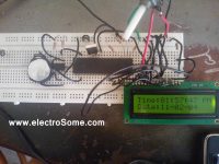
Make connections according to the above circuit diagram.
- Connect VCC pin of sensor to 5V power supply of Arduino,
- Connect GND pin of sensor to GND of Arduino and
- Connect Analog output pin of sensor to A0 pin of Arduino.
Upload the above code into Arduino IDE and test the result on Serial Monitor by soaking the rain sensor into water.
The serial monitor displays the below result based on the amount water drop on the rain sensor module.
- If the Rain Sensor Board is completely soaked; “case 0” will be activated and “RAINING” will be sent to the serial monitor.
- If the Sensor Board has water droplets on it; “case 1” will be activated and “RAIN WARNING” will be sent to the serial monitor.
- If the Sensor Board is dry; “case 2″ will be activated and “NOT RAINING ” will be sent to the serial monitor.
Practical Implementation


Try adjusting the sensitivity of the sensor.
Sir, i had try this but why i only got case 2 (not raining)and case 1(rain warning). Even i soaked that rain sensor in water only case 1 appeared. i wonder why.