

Interfacing HC-SR04 Ultrasonic Sensor with PIC Microcontroller
Contents
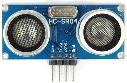
HC-SR04 Ultrasonic Distance Sensor is a popular and low cost solution for non-contact distance measurement function. It is able to measure distances from 2cm to 400cm with an accuracy of about 3mm. This module includes ultrasonic transmitter, ultrasonic receiver and its control circuit.
HC-SR04 module has 4 pins :
- VCC – 5V, +ive of the power supply
- TRIG – Trigger Pin
- ECHO – Echo Pin
- GND – -ive of the power supply
TRIG and ECHO pins can be used to interface this module with a microcontroller unit. These are TTL (0 – 5V) input output pins.
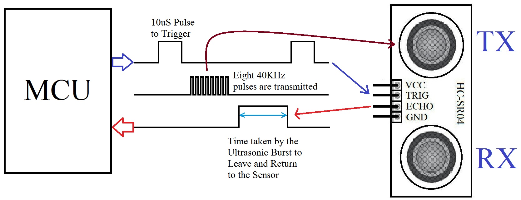
HC-SR04 Ultrasonic Module Working
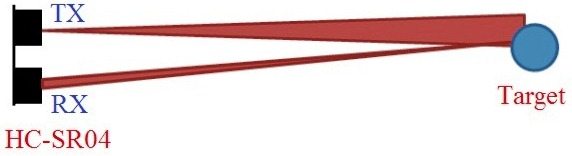
- Provide TRIGGER signal, atleast 10μS High Level (5V) pulse.
- The module will automatically transmit eight 40KHz ultrasonic burst.
- If there is an obstacle in-front of the module, it will reflect the ultrasonic burst.
- If the signal is back, ECHO output of the sensor will be in HIGH state (5V) for a duration of time taken for sending and receiving ultrasonic burst. Pulse width ranges from about 150μS to 25mS and if no obstacle is detected, the echo pulse width will be about 38ms.
Interfacing with PIC Microcontroller
Circuit Diagram
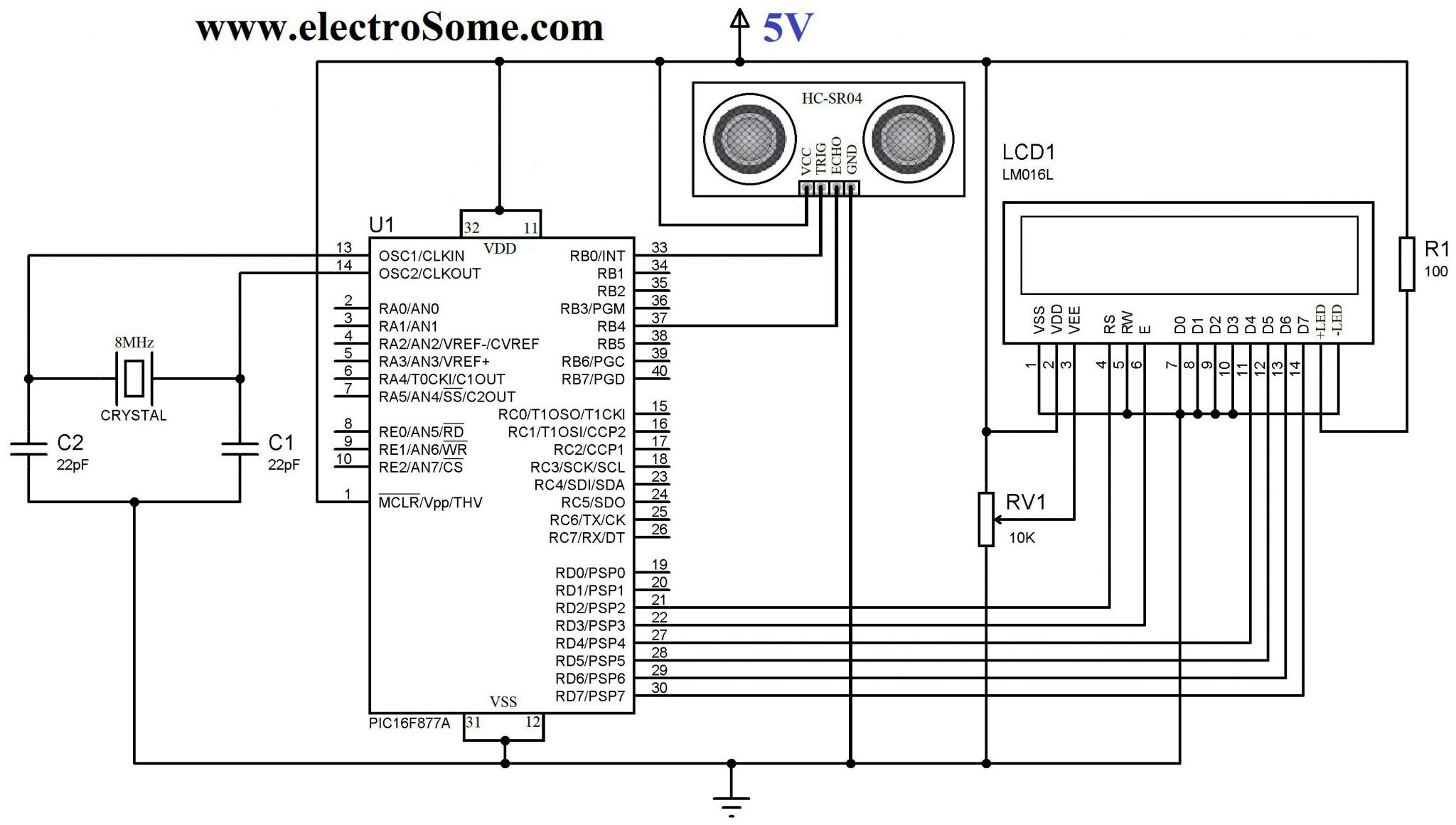
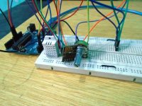
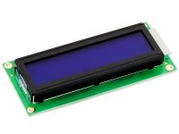
PIC 16F877A is the heart of this circuit. VDD and VSS of PIC Microcontroller is connected to +5V and GND respectively which will provide necessary power for its operation. A 8MHz crystal is connected to OSC1 and OSC2 pins of PIC, to provide clock for its operation. 22pF capacitors connected along with the crystal will stabilize the oscillations generated by the crystal. 16×2 LCD is connected to PORTD which is interfaced using 4 bit mode communication. 10KΩ preset is used to adjust the contrast of the LCD. A 100Ω resistor is used to limit current through the LCD back-light LED.
TRIGGER pin of HC-SR04 sensor is connected to RB0 (pin 33) of PIC which is to be configured as an Output PIN (TRIS bit is 0) and ECHO pin is connected to RB4 (pin 37) which is to be configured as an Input PIN (TRIS bit is 1).
Programming
Basic Steps :
- Provide TRIGGER to ultrasonic module
- Listen for Echo
- Start Timer when ECHO HIGH is received
- Stop Timer when ECHO goes LOW
- Read Timer Value
- Convert it to Distance
- Display it
Timer1 Module
Timer1 Module can be used as a 16 bit counter or timer. It consists of two 8 bit registers TMR1H and TMR1L which are readable and writable. The register pair, TMR1H:TMR1L increments from 0000H to FFFFH and rolls over to 0000H. If enabled Timer1 Overflow Interrupt is generated during rolls over to 0000H. Here we will use this module as a 16 bit Timer.
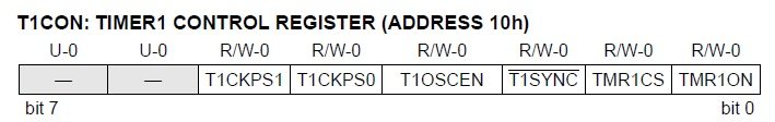
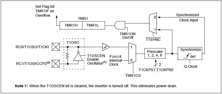
Since we are using Timer1 module as a Timer, we should use internal clock (Fosc/4), ie TMR1CS = 0. Prescaler is used to divide the internal clock (Fosc/4). Here we can set Prescaler as 2, ie T1CKPS1 = 0 & T1CKPS0 = 1. T1SYNC bit is ignored when TMR1CS = 0. As we are using internal clock (Fosc/4) we can disable oscillator, ie T1OSEN = 0. TMR1ON bit can be used to ON or OFF timer as per our requirements.
- Thus we can initialize timer as : T1CON = 0x10
- To TURN ON the Timer : T1CON.F0 = 1 or TMR1ON = 1
- To TURN OFF the Timer : T1CON.F0 = 0 or TMR1ON = 0
Fosc is the oscillator frequency, here we are using 8MHz crystal hence Fosc = 8MHz.
Time = (TMR1H:TMR1L)*(1/Internal Clock)*Prescaler
Internal Clock = Fosc/4 = 8MHz/4 = 2MHz
Therefore, Time = (TMR1H:TMR1L)*2/(2000000) = (TMR1H:TMR1L)/1000000
Distance Calculation
- Distance = Speed * Time
- Let d be the distance between Ultrasonic Sensor and Target
- Total distance traveled by the ultrasonic burst : 2d (forward and backward)
- Speed of Sound in Air : 340 m/s = 34000 cm/s
- Thus, d = (34000*Time)/2, where Time = (TMR1H:TMR1L)/(1000000)
- Therefore, d = (TMR1H:TMR1L)/58.82 cm
- TMR1H:TMR1L = TMR1L | (TMR1H<<8)
Simple Method – MikroC & MPLAB XC8 Program
MikroC Code
// LCD module connections
sbit LCD_RS at RD2_bit;
sbit LCD_EN at RD3_bit;
sbit LCD_D4 at RD4_bit;
sbit LCD_D5 at RD5_bit;
sbit LCD_D6 at RD6_bit;
sbit LCD_D7 at RD7_bit;

sbit LCD_RS_Direction at TRISD2_bit;
sbit LCD_EN_Direction at TRISD3_bit;
sbit LCD_D4_Direction at TRISD4_bit;
sbit LCD_D5_Direction at TRISD5_bit;
sbit LCD_D6_Direction at TRISD6_bit;
sbit LCD_D7_Direction at TRISD7_bit;
// End LCD module connections

void main()
{
  int a;
  char txt[7];
  Lcd_Init();
  Lcd_Cmd(_LCD_CLEAR);          // Clear display
  Lcd_Cmd(_LCD_CURSOR_OFF);     // Cursor off

  TRISB = 0b00010000;           //RB4 as Input PIN (ECHO)

  Lcd_Out(1,1,"Developed By");
  Lcd_Out(2,1,"electroSome");

  Delay_ms(3000);
  Lcd_Cmd(_LCD_CLEAR);

  T1CON = 0x10;                 //Initialize Timer Module

  while(1)
  {
    TMR1H = 0;                  //Sets the Initial Value of Timer
    TMR1L = 0;                  //Sets the Initial Value of Timer

    PORTB.F0 = 1;               //TRIGGER HIGH
    Delay_us(10);               //10uS Delay
    PORTB.F0 = 0;               //TRIGGER LOW

    while(!PORTB.F4);           //Waiting for Echo
    T1CON.F0 = 1;               //Timer Starts
    while(PORTB.F4);            //Waiting for Echo goes LOW
    T1CON.F0 = 0;               //Timer Stops

    a = (TMR1L | (TMR1H<<8));   //Reads Timer Value
    a = a/58.82;                //Converts Time to Distance
    a = a + 1;                  //Distance Calibration
    if(a>=2 && a<=400)          //Check whether the result is valid or not
    {
      IntToStr(a,txt);
      Ltrim(txt);
      Lcd_Cmd(_LCD_CLEAR);
      Lcd_Out(1,1,"Distance = ");
      Lcd_Out(1,12,txt);
      Lcd_Out(1,15,"cm");
    }
    else
    {
      Lcd_Cmd(_LCD_CLEAR);
      Lcd_Out(1,1,"Out of Range");
    }
    Delay_ms(400);
  }
}
MPLAB XC8 Code
#define _XTAL_FREQ 8000000

#define RS RD2
#define EN RD3
#define D4 RD4
#define D5 RD5
#define D6 RD6
#define D7 RD7

#include <xc.h>
#include "lcd.h";
#include <pic16f877a.h>

// BEGIN CONFIG
#pragma config FOSC = HS
#pragma config WDTE = OFF
#pragma config PWRTE = OFF
#pragma config BOREN = ON
#pragma config LVP = OFF
#pragma config CPD = OFF
#pragma config WRT = OFF
#pragma config CP = OFF
//END CONFIG
void main()
{
  int a;

  TRISB = 0b00010000;         //RB4 as Input PIN (ECHO)
  TRISD = 0x00;               // LCD Pins as Output

  Lcd_Init();

  Lcd_Set_Cursor(1,1);
  Lcd_Write_String("Developed By");
  Lcd_Set_Cursor(2,1);
  Lcd_Write_String("electroSome");

  __delay_ms(3000);
  Lcd_Clear();

  T1CON = 0x10;               //Initialize Timer Module

  while(1)
  {
    TMR1H = 0;                //Sets the Initial Value of Timer
    TMR1L = 0;                //Sets the Initial Value of Timer

    RB0 = 1;                  //TRIGGER HIGH
    __delay_us(10);           //10uS Delay
    RB0 = 0;                  //TRIGGER LOW

    while(!RB4);              //Waiting for Echo
    TMR1ON = 1;               //Timer Starts
    while(RB4);               //Waiting for Echo goes LOW
    TMR1ON = 0;               //Timer Stops

    a = (TMR1L | (TMR1H<<8)); //Reads Timer Value
    a = a/58.82;              //Converts Time to Distance
    a = a + 1;                //Distance Calibration
    if(a>=2 && a<=400)        //Check whether the result is valid or not
    {
      Lcd_Clear();
      Lcd_Set_Cursor(1,1);
      Lcd_Write_String("Distance = ");

      Lcd_Set_Cursor(1,14);
      Lcd_Write_Char(a%10 + 48);

      a = a/10;
      Lcd_Set_Cursor(1,13);
      Lcd_Write_Char(a%10 + 48);

      a = a/10;
      Lcd_Set_Cursor(1,12);
      Lcd_Write_Char(a%10 + 48);

      Lcd_Set_Cursor(1,15);
      Lcd_Write_String("cm");
    }
    else
    {
      Lcd_Clear();
      Lcd_Set_Cursor(1,1);
      Lcd_Write_String("Out of Range");
    }
    __delay_ms(400);
  }
}
This program uses our LCD Library for MPLAB XC8. You need to download and include the header file “lcd.h”. For more information please read the tutorial, Interfacing LCD with PIC Microcontroller – MPLAB XC8.
I hope that you can understand the working of the above program through comments. If you have any doubts, just comment below.
Distance Calibration
For accurate distance measuring you may calibrate the obtained result. Here for making the displayed distance more accurate, I added 1 to the the measured distance. This constant of calibration can be find using a series of practical experiments with a ruler scale.
In the above program there is a small problem as it infinitely waiting for ECHO and to ECHO goes LOW. If HIGH echo pulse is not received due to any reason, the program may get stuck there. So it is not a good practice to infinitely wait for ECHO and to ECHO goes LOW. The best solution is to use PORTB On-Change Interrupt feature of PIC Microcontroller.
PORTB On-Change Interrupt
Four pins of PORTB (RB4 – RB7) have interrupt on-change feature. Only those pins configured as INPUT PIN can cause this Interrupt while this interrupt is enabled. If the Logic State of any of these four pin changes (only Input Pins), interrupt will be generated.
PORTB On-Change Interrupt can be enabled by :
- Set Global Interrupt Enable bit : INTCON.GIE = 1
- Set PORTB On-Change Interrupt Enable Bit : INTCON.RBIE = 1
Note : PORTB On-Change Interrupt flag (INTCON.RBIF) will be set whenever this interrupt is generated and it should be cleared in software
Using Interrupt – MikroC & MPLAB XC8 Program
MikroC Code
// LCD module connections
sbit LCD_RS at RD2_bit;
sbit LCD_EN at RD3_bit;
sbit LCD_D4 at RD4_bit;
sbit LCD_D5 at RD5_bit;
sbit LCD_D6 at RD6_bit;
sbit LCD_D7 at RD7_bit;

sbit LCD_RS_Direction at TRISD2_bit;
sbit LCD_EN_Direction at TRISD3_bit;
sbit LCD_D4_Direction at TRISD4_bit;
sbit LCD_D5_Direction at TRISD5_bit;
sbit LCD_D6_Direction at TRISD6_bit;
sbit LCD_D7_Direction at TRISD7_bit;
// End LCD module connections

volatile int a;

//Interrupt function will be automatically executed on Interrupt
void interrupt()
{
  if(INTCON.RBIF == 1)                 //Makes sure that it is PORTB On-Change Interrupt
  {
    INTCON.RBIE = 0;                   //Disable On-Change Interrupt
    if(PORTB.F4 == 1)                  //If ECHO is HIGH
      T1CON.F0 = 1;                    //Start Timer
    if(PORTB.F4 == 0)                  //If ECHO is LOW
    {
      T1CON.F0 = 0;                    //Stop Timer
      a = (TMR1L | (TMR1H<<8))/58.82;  //Calculate Distance
    }
  }
  INTCON.RBIF = 0;                     //Clear PORTB On-Change Interrupt flag
  INTCON.RBIE = 1;                     //Enable PORTB On-Change Interrupt
}

void main()
{
  char txt[7];
  Lcd_Init();
  Lcd_Cmd(_LCD_CLEAR);                 // Clear display
  Lcd_Cmd(_LCD_CURSOR_OFF);            // Cursor off

  TRISB = 0b00010000;
  INTCON.GIE = 1;                      //Global Interrupt Enable
  INTCON.RBIF = 0;                     //Clear PORTB On-Change Interrupt Flag
  INTCON.RBIE = 1;                     //Enable PORTB On-Change Interrupt

  Lcd_Out(1,1,"Developed By");
  Lcd_Out(2,1,"electroSome");

  Delay_ms(3000);
  Lcd_Cmd(_LCD_CLEAR);

  T1CON = 0x10;                        //Initializing Timer Module

  while(1)
  {
    TMR1H = 0;                         //Setting Initial Value of Timer
    TMR1L = 0;                         //Setting Initial Value of Timer

    a = 0;

    PORTB.F0 = 1;                      //TRIGGER HIGH
    Delay_us(10);                      //10uS Delay
    PORTB.F0 = 0;                      //TRIGGER LOW

    Delay_ms(100);                     //Waiting for ECHO
    a = a + 1;                         //Error Correction Constant
    if(a>2 && a<400)                   //Check whether the result is valid or not
    {
      IntToStr(a,txt);
      Ltrim(txt);
      Lcd_Cmd(_LCD_CLEAR);
      Lcd_Out(1,1,"Distance = ");
      Lcd_Out(1,12,txt);
      Lcd_Out(1,15,"cm");
    }
    else
    {
      Lcd_Cmd(_LCD_CLEAR);
      Lcd_Out(1,1,"Out of Range");
    }
    Delay_ms(400);
  }
}
MPLAB XC8 Code
#define _XTAL_FREQ 8000000

#define RS RD2
#define EN RD3
#define D4 RD4
#define D5 RD5
#define D6 RD6
#define D7 RD7

#include <xc.h>
#include "lcd.h";
#include <pic16f877a.h>

// BEGIN CONFIG
#pragma config FOSC = HS
#pragma config WDTE = OFF
#pragma config PWRTE = OFF
#pragma config BOREN = ON
#pragma config LVP = OFF
#pragma config CPD = OFF
#pragma config WRT = OFF
#pragma config CP = OFF
//END CONFIG

volatile int a;

void interrupt echo()
{
  if(RBIF == 1)                       //Makes sure that it is PORTB On-Change Interrupt
  {
    RBIE = 0;                         //Disable On-Change Interrupt
    if(RB4 == 1)                      //If ECHO is HIGH
    TMR1ON = 1;                       //Start Timer
    if(RB4 == 0)                      //If ECHO is LOW
    {
      TMR1ON = 0;                     //Stop Timer
      a = (TMR1L | (TMR1H<<8))/58.82; //Calculate Distance
    }
  }
  RBIF = 0;                           //Clear PORTB On-Change Interrupt flag
  RBIE = 1;                           //Enable PORTB On-Change Interrupt
}
void main()
{
  TRISB = 0b00010000;                 //RB4 as Input PIN (ECHO)
  TRISD = 0x00;                       // LCD Pins as Output
  GIE = 1;                            //Global Interrupt Enable
  RBIF = 0;                           //Clear PORTB On-Change Interrupt Flag
  RBIE = 1;                           //Enable PORTB On-Change Interrupt

  Lcd_Init();

  Lcd_Set_Cursor(1,1);
  Lcd_Write_String("Developed By");
  Lcd_Set_Cursor(2,1);
  Lcd_Write_String("electroSome");

  __delay_ms(3000);
  Lcd_Clear();

  T1CON = 0x10;                       //Initialize Timer Module

  while(1)
  {
    TMR1H = 0;                        //Sets the Initial Value of Timer
    TMR1L = 0;                        //Sets the Initial Value of Timer

    RB0 = 1;                          //TRIGGER HIGH
    __delay_us(10);                   //10uS Delay
    RB0 = 0;                          //TRIGGER LOW

    __delay_ms(100);                  //Waiting for ECHO
    a = a + 1;                        //Error Correction Constant

    if(a>=2 && a<=400)                //Check whether the result is valid or not
    {
      Lcd_Clear();
      Lcd_Set_Cursor(1,1);
      Lcd_Write_String("Distance = ");

      Lcd_Set_Cursor(1,14);
      Lcd_Write_Char(a%10 + 48);

      a = a/10;
      Lcd_Set_Cursor(1,13);
      Lcd_Write_Char(a%10 + 48);

      a = a/10;
      Lcd_Set_Cursor(1,12);
      Lcd_Write_Char(a%10 + 48);

      Lcd_Set_Cursor(1,15);
      Lcd_Write_String("cm");
    }
    else
    {
      Lcd_Clear();
      Lcd_Set_Cursor(1,1);
      Lcd_Write_String("Out of Range");
    }
    __delay_ms(400);
  }
}
This program uses our LCD Library for MPLAB XC8. You need to download and include the header file “lcd.h”. For more information please read the tutorial, Interfacing LCD with PIC Microcontroller – MPLAB XC8.
Download
You can download entire project files here.
- Interfacing HC-SR04 with PIC Microcontroller – MikroC Pro
- Interfacing HC-SR04 with PIC Microcontroller – MPLAB XC8


Very good tutorial an the HC-SR04 – just some remarks:
1) To avoid unexpected behaviour/results always use “volatile” for variables in context with interrupt routines:
volatile unsigned int a;
instead of:
int a; // there are no negative numbers, so use “unsigned int”
2) always add a counter to check how many times there was a timer overflow to get a correct result (even if in this case an overflow may not be expected)
3) for measuring a pulse width you may also use the capture mode of the CCP module of your PIC (if available)
It is already explained above.
https://electrosome.com/hc-sr04-ultrasonic-sensor-pic/#Timer1_Module
Yes you can add another one. Just read data from each sensors one by one instead of doing simultaneously. When you do it fast, it will appear as simultaneous for us.
48 is the ASCII value of character ‘0’. Basically here we are converting an integer to corresponding character.
It is already explained above. Please read from below section.
https://electrosome.com/hc-sr04-ultrasonic-sensor-pic/#Timer1_Module
Yes it does, however you will have to make some subtle changes. For example, instead of simply typing “RBIF”, you will need to type “INTCONbits.RBIF”. There are many place you will need to do this in the code, including doing the same thing with “TMR1ON” which you would frame as “T1CONbits.TMR1ON”. Once you do that you should be fine. If you paste your code I will be able to tell you exactly how to frame it. Otherwise simply search the word following PIC18 and the syntax should come up on some forum.
Hello. Thank you for providing this amazing tutorial, it is indeed very helpful.
Will this program work with the PIC18F4620?
Will this ultra-sonic sensor work for a tank having depth of 3-5 feet ?
Can someone please explain to me how this was derived? d = (TMR1H:TMR1L)/58.82 cm
especially the 58.82 part. I’m using a 20Mhz osci and I need to calculate my own values to use, but I don’t understand how.
What‘s difference between the simple and using interrupt methods? does the second method will be more accurate and real-time reaction than the first simple loop one? thanks
What’s the meaning of “Lcd_Write_Char(a%10 + 48)”, especially the “+48”? thanks!
Hi just a small question, can ADC also be used when using the Timer1? or does it cause problems? Many thanks and your tutorials are very good 🙂
please
@Ligo George can you send me sumilation in isis proteus
void interrupt echo()
{
if(RBIF == 1){ //Makes sure that it is PORTB On-Change Interrupt
RBIE = 0; //Disable On-Change Interrupt
if(RB4 == 1) //If ECHO is HIGH
TMR1ON = 1; //Start Timer
if(RB4 == 0) //If ECHO is LOW
{
TMR1ON = 0; //Stop Timer
a = (TMR1L | (TMR1H<<8))/58.82; //Calculate Distance } if(RB5 == 1) //If ECHO is HIGH TMR1ON = 1; //Start Timer if(RB5 == 0) //If ECHO is LOW { TMR1ON = 0; //Stop Timer b = (TMR1L | (TMR1H<<8))/58.82; //Calculate Distance } RBIF = 0; //Clear PORTB On-Change Interrupt flag RBIE = 1; //Enable PORTB On-Change Interrupt } is it possible to add a new HC-sr by doing this and using other 10us trigger function?
It is corrected. Thanks.
Please correct this line
a = a + 1; //Distance Calibration
Remove the at the end, kept me guessing for a while
Perhaps a mention to include the Libraries for Conversion, C String and and LCD might help some others.
Thanks
Sorry, can you please elaborate ?
Which compiler you are using ?
You might need to make some changes based on the register map of PIC 16F1829. Please refer the datasheet for more information.
Do we put the interrupt and lcd in a separate source file and the ping sensor in a separate source file?
Hello. Will this code work with the pic16f1829 if the ports changed?
It is using PORTB on change interrupt….. Not normal interrupt pin.
It is correct only. Here we are using PORTB on change interrupt, not general interrupt pin RB0.
can someone tell me why is he dividing (time)/58cm for distance? distance formula is supposed to be speed*time. and where did the 58 come from? thanks for the help
hi guys; tried this code on the PIC16F877A and it works well. I’m using it in an application where I need to monitor a liquid level. A decrease in the liquid level (increase in distance) needs to trigger another routine.
Could somebody please tell me how I can go about doing this. I know it sounds easy but I just can’t seem to do it. I’m using MPLABX, XC8. thanks in advance
I need to talk directly to the one who put the circuit
I’ll tell you where is the problem
NOBODY ever tried the circuit because it has a awful error!!!!!
he said that we should connect the ECHO pin to the interrupt pin directly but he has done the exact opposit
but this does not mean that the written program is written correct (which I do not understand!)
So my friend where is the use of the interrupt???!!!!
but it works but we did not learn any thing from it!
adjust the microcontroller settings you are not sellecting the specified microcontroller
believe me I have faced this same error
I’ll tell you where is the problem
NOBODY ever tried the circuit because it has a awful error!!!!!
he said that we should connect the ECHO pin to the interrupt pin directly but he has done the exact opposit
but this does not mean that the written program is written correct (which I do not understand!)
good evening dr. ligo
may you modify the code of the ultrasonic sensors to 6 sensors and the results will go to the raspberry pi through spi using mplab x xc8
also, may you give me ur email???
thanks
i am waiting ur replay
faithful: john
I am using MikroC 6.6.3 and modified your code little bit
want to control my motor on interrupt using ultrasound sensor that you used in your tutorial but when i complied my code it gives the error that ” ‘a’ Identifier redefined ”
I am pasting the code
motors are not properly reversing after getting the interrupt if I declare that “int a” inside the void interrupt()
I am using 18F452 PIC micrfocontroller
void Motor1_forward();
void Motor1_backward();
void Motor2_forward();
void Motor2_backward();
void Motor1_stop();
void Motor2_stop();
int a;
void interrupt()
{
//int a;
if(INTCON.RBIF == 1) //Makes sure that it is PORTB On-Change Interrupt
{
INTCON.RBIE = 0; //Disable On-Change Interrupt
if(PORTB.F4 == 1) //If ECHO is HIGH
T1CON.F0 = 1; //Start Timer
if(PORTB.F4 == 0) //If ECHO is LOW
{
T1CON.F0 = 0; //Stop Timer
a = (TMR1L | (TMR1H<<8))/58.82; //Calculate Distance
if (a2 && a<400) //Check whether the result is valid or not
// { //Check whether the result is valid or not
// Motor1_backward();
// Motor2_backward();
// }
/* Motor1_forward();
Motor2_forward();
Delay_ms(2000);
Motor1_stop();
Motor2_stop();
Delay_ms(1000);
Motor1_backward();
Motor2_backward();
Delay_ms(2000);
Motor1_stop();
Motor2_stop();
Delay_ms(1000); */
}while(1);
}
void Motor1_forward()
{
PORTB.B1 = 1; // Forward Motion
PORTB.B2 = 0;
}
void Motor1_backward()
{
PORTB.B1 = 0; // Backward Motion
PORTB.B2 = 1;
}
void Motor2_forward()
{
PORTB.B3 = 0; // Forward Motion
PORTB.B5 = 1;
}
void Motor2_backward()
{
PORTB.B3 = 1; // Backward Motion
PORTB.B5 = 0;
}
void Motor1_stop()
{
PORTB.B1 = 0; // Stop
PORTB.B2 = 0;
}
void Motor2_stop()
{
PORTB.B3 = 0; // Stop
PORTB.B5 = 0;
}
Hi, good work. I have a question for you. What would be the modification to make the code so that the value of the distance has two decimal precision on the LCD. I use Mikroc. And sorry for my English.
What is the meaning of this : d = (TMR1H:TMR1L)/58.82 cm.
And What is the meaning of: TMR1H:TMR1L = TMR1L | (TMR1H<<8)
Hello, thanks for answered, what changes I need to make it work.?
Same code won’t work for other microcontrollers. You need to make necessary changes as required.
Hello, I tried to do this. I used PIC 16F887 microcontroller and used the same ports of your sample, but it doesn’t work. This example I didn´t include LDC Display, my only indicator is a LED. When a object is nerby LED turns on.
It is just an update interval.
You need to make necessary modfications for that.
Question why do we need the 400 ms delay at the end. Thanks
I am only trying to find distance without LCD display. But a using pic16f690 it has an preset internal clock of 4 MHz will your code work or do I have to modify it. I am using Mikroc for programming
It is MPLAB X IDE XC8 code only.
hello . please can i have the code program for MPLAB X IDE v3.40
pic16f877a
hello . please can i have the code program for MPLAB X IDE v3.40
The above project is done using PIC 16F877A. If you are using PIC 18F26K22, you might need to make a lot of necessary changes.
Please use use our forums https://electrosome.com/forums/ for free technical support.
If you need premiums project support, just drop a mail to [email protected]
I didn’t tested above code in 16F887. It a different IC so there might be some changes that you need to make.
Please give more information if you need help. You may use our forums also : https://electrosome.com/forums/
You can contact us if you need premium support.
HC-SR04 won’t work for 1000cm.
Kindly use our forums ( https://electrosome.com.com/forums/ ) for asking technical questions.
You can contact us if you need premium support.
You need the adjust the timer prescaler depending on the pic and clock frequency you are using.
Yes, the MPLAB XC8 code you can use.
i tried to use the code of interrupt in above in 16f887 but it didn’t
work . although the register of both ic are same…. Why ??? (I.E i used both ANSEL register zero for digital input )
Hi,Ligo George,thanks for the code.I used your logic to display the distance after every 1s on a serial terminal ‘hterm’.i used PIC18F26K22.The problem is I get decimal values like 2,3,4,5 on the serial terminal,which do not match with the actual distance I am measuring.Also the output changes by itself even when the distance to object is kept constant.Can you help?
en lugar de poner 58.82 tienes que poner 147.058824
hello sir…i have done make this project..but can add the distance 400 cm to 1000 cm or more
Hi ligo can u please give me your mail id
i have some doubts regarding a project using RF communication
can u please help me in suggesting!..
Dear Experts,
I have just finished my project for measuring the distance using HC-SR04.
My project is similar with the one described in this page.
I used PIC 18F452 with 4 MHz HS crystal oscillator.
I cannot understand why the code is not working without repeating the line:
“dist = (TMR1L | (TMR1H<<8))/59; //Calculate Distance"
Could you please find a explanation and share it to me?
I found this solution by chance when I double written that line by mistake.
Thank you in advance!
Adrian
Full code:
// LCD module connections
sbit LCD_RS at RD2_bit;
sbit LCD_EN at RD3_bit;
sbit LCD_D4 at RD4_bit;
sbit LCD_D5 at RD5_bit;
sbit LCD_D6 at RD6_bit;
sbit LCD_D7 at RD7_bit;
sbit LCD_RS_Direction at TRISD2_bit;
sbit LCD_EN_Direction at TRISD3_bit;
sbit LCD_D4_Direction at TRISD4_bit;
sbit LCD_D5_Direction at TRISD5_bit;
sbit LCD_D6_Direction at TRISD6_bit;
sbit LCD_D7_Direction at TRISD7_bit;
// End LCD module connections
int time;
int dist;
//Interrupt function will be automatically executed on Interrupt
void interrupt()
{
if(INTCON.RBIF == 1) //Makes sure that it is PORTB On-Change Interrupt
{
INTCON.RBIE = 0; //Disable On-Change Interrupt
if(PORTB.F4 == 1) //If ECHO is HIGH
T1CON.F0 = 1; //Start Timer
if(PORTB.F4 == 0) //If ECHO is LOW
{
T1CON.F0 = 0; //Stop Timer
dist = (TMR1L | (TMR1H<<8))/59; //Calculate Distance ????
dist = (TMR1L | (TMR1H<<8))/59; //Calculate Distance
time = (TMR1L | (TMR1H<2 && dist<400) //Check whether the result is valid or not
{
dist = dist + 1; //Error Correction Constant
IntToStr(dist,txt);
Ltrim(txt);
Lcd_Out(1,1,"Distance = ");
Lcd_Out(1,12,txt);
Lcd_Out(1,15,"cm");
}
else
{
Lcd_Cmd(_LCD_CLEAR);
Lcd_Out(1,1,"Out of Range");
}
IntToStr(time,txt);
Ltrim(txt);
Lcd_Out(2,1,"Time = ");
Lcd_Out(2,8,txt);
Delay_ms(400);
}
}
do you have the code in mplab ide form? i mean code to generate using mplab ide
p/s : sorry for bad english
Sorry, we don’t have any proteus library for HC-SR04.
Yes ofcourse. For simple method you can use PORTC.
No, you might need to make some modifications.
Hello,
Above project is 100% working. Voltage on pins will vary depends on the type of signal on it.
First try some LED blinking projects and verify everything is working fine.
Yes, if you understand above project, you can easily do it.
NO.
<<8 means shift 8 bits left.
Those are cheap chinese modules. I don’t think it will have the quality for that purpose.
This project is 100% working in real hardware. We didn’t simulated it.
Simulation ?
Which software you used for simulation ?
It is 100% working in hardware. We didn’t simulated it.
Sorry, we don’t have any codes for AVR/Atmega. This is for PIC microcontrollers only. You can take the program logic.
Can i ask for the proteus library of hcsr04?I cant find anything that is not arduino compatible
I thank you for the program. Can I use the simple method with PORTC instaed of PORTB?
Hello.. Do this code compatible with PIC 18F45K22?
Hello, i have done the exact schematics and i have loaded the PIC16F877A with your hex (i have tried both versions)but all the PIC pins have between the 0.8V and 1V. The display even disconnected from the PIC it shows the below line fully black. Any suggestion? I’m programming the PIC with a Velleman K8076. Am i doing something wrong? What could cause this? I have also a PIC18F4550 and i have tried the same with the suggestions within the comments but still sam issue… I initially suspected the programmer kit but after being able to read from the chip the hex that i just downloaded it did not made any sense..
how can i write a code for hc-sr04 with led and buzzer instead of ldr? can you help plz?
(TMR1H<<8)) what is the meaning of it??? is 8 is for fosc?
#include
#include
#include”delay.h”
#include”config.h”
#include”uart.h”
#include”lcd.h”
#define Fosc 20000000 /* External crystal frequency */
#define baud 9600 /* UART baud rate */
#define config2 ((Fosc/baud/64)-1)
unsigned char config1 = (USART_TX_INT_OFF & USART_RX_INT_OFF & USART_ASYNCH_MODE & USART_EIGHT_BIT & USART_CONT_RX & USART_BRGH_LOW);
int a;
void interrupt echo()
{
if(RBIF == 1) //Makes sure that it is PORTB On-Change Interrupt
{
RBIE = 0; //Disable On-Change Interrupt
if(RB4 == 1) //If ECHO is HIGH
TMR1ON = 1; //Start Timer
if(RB4 == 0) //If ECHO is LOW
{
TMR1ON = 0; //Stop Timer(TMR1L | (TMR1H<<8));
a = (TMR1L| (TMR1H<=2 && a<=400)
{
Write_str("distance =");
Write_LCD("Distance= ");
Write(a/100 + 48);
Data(a/100 +48);
// Command(0x80);
a = a%100;
Write(a/10 + 48);
Data(a/10 + 48);
//Command(0x80);
a = a%10;
Write(a+48);
Data(a+48);
Write_LCD(" cm ");
Command(0x80);
}
else
{
Write_str("Out of Range");
Write_LCD("out of range");
Command(0x80);
}
delay_ms(400);
}
}
ligo what about using HC sr-04 for some semi industrial applications
you need to rename,config bits ,name of timer registers
change the things like TRIS to DDRA
include AVR header files
and please cheak atmega 32 have interrupt on-change feature
if not follow the first program.
logic is same as above .
hi, im testing it in proteus, everything looks fine but after abaut 14sec i have error. And proteus just turn’s off. Can you help me solve the problem ?
i have error after 14 sec of simulation , like cannot find source at adress 00000079
Can this code be used with avr and/ atmega32 using Mikroc pro avr 2015 build6.1.0? what changes have to do?
if only change TRIS to DDR,can i use?
what does fusebits means?
Plz help
thanks ligo
It is 100% working as in the video.
We can’t help without more details.
For PIC 18F it is better to replace all output PORT operations with LAT register.
Just calculate with equations explained above.
you need to add header files for both delay and UART and also setup the config bits
This is not working for me.pls help me
Hi i am doing this program with Pic24.
I have written the following Program and checking its output on Tera Term
But I am not able to get the Sensor Output
If Anybody can help
Here’s the program
#include “pic24_all.h”
#include
/** file
* Measures the pulse width of a pushbutton switch using Timer2 without input capture.
* CLOCK_CONFIG=PRIPLL_8MHzCrystal_40MHzFCY is defined in the MPLAB project.
* Remove this macro if you wish to use the internal oscillator.
*/
#define R2 _LATB2
#define CONFIG_R2_DIG_OUTPUT() CONFIG_RB2_AS_DIG_OUTPUT()
void CONFIG_ROW() {
CONFIG_R2_DIG_OUTPUT();
//CONFIG_R2_DIG_OUTPUT();
}
inline void CONFIG_SW1() {
CONFIG_RB13_AS_DIG_INPUT(); //use RB13 for switch input
ENABLE_RB13_PULLUP(); //enable the pullup
}
#define SW1 _RB13 //switch state
#define SW1_PRESSED() SW1==0 //switch test
#define SW1_RELEASED() SW1==1 //switch test
void configTimer2(void) {
T2CON = T2_OFF | T2_IDLE_CON | T2_GATE_OFF
| T2_32BIT_MODE_OFF
| T2_SOURCE_INT
| T2_PS_1_256 ; //at 40 MHz, approx 420 ms period, 1 tick = 6.4 us
PR2 = 0xFFFF; //maximum period
TMR2 = 0; //clear timer2 value
_T2IF = 0; //clear interrupt flag
T2CONbits.TON = 1; //turn on the timer
}
/// Switch1 configuration
int main (void) {
CONFIG_ROW();
uint16_t u16_start, u16_delta;
uint32_t u32_pulseWidth;
configBasic(HELLO_MSG);
CONFIG_SW1(); //use RB13
R2 = 1;
DELAY_US(10);
R2 = 0;
configTimer2();
while (1) {
//outString(“Press button…”);
while (SW1_RELEASED())doHeartbeat();
u16_start = TMR2;
while (SW1_PRESSED())doHeartbeat();
u16_delta = TMR2 – u16_start; //works because using maximum PR2 value
u32_pulseWidth = ticksToUs((uint32_t) u16_delta,getTimerPrescale(T2CONbits));
u32_pulseWidth = (u32_pulseWidth/58);// DISTANCE IN CM
printf(” %ld usn”,u32_pulseWidth);
DELAY_MS(100);
}
}
1:2
For pic 18f4550 mplab xc8
// add uart lib -(* _ *)-
thanks LIGO for this awesome -(* _ *)-
//Time = (TMR1H:TMR1L)*(1/Internal Clock)*Prescaler
//internal clock=fosc/4 ie, your crystal freq/4
#include
#include
#include”delay.h”
#include”config.h”
#include”uart.h”
#define Fosc 20000000 /* External crystal frequency */
#define baud 9600 /* UART baud rate */
#define config2 ((Fosc/baud/64)-1)
unsigned char config1 = (USART_TX_INT_OFF & USART_RX_INT_OFF & USART_ASYNCH_MODE & USART_EIGHT_BIT & USART_CONT_RX & USART_BRGH_LOW);
int a;
void interrupt echo()
{
if(RBIF == 1) //Makes sure that it is PORTB On-Change Interrupt
{
RBIE = 0; //Disable On-Change Interrupt
if(RB4 == 1) //If ECHO is HIGH
TMR1ON = 1; //Start Timer
if(RB4 == 0) //If ECHO is LOW
{
TMR1ON = 0; //Stop Timer(TMR1L | (TMR1H<<8));
// config for timer with a 20MHz crystal
a = (TMR1L| (TMR1H<=2 && a<=400)
{
Write_str("distance =");
Write(a/100 + 48);
a = a%100;
Write(a/10 + 48);
a = a%10;
Write(a+48);
}
else
{
Write_str("Out of Range");
}
delay_ms(400);
}
}
Sry with pic16f877a
Hey what will be the value of prescaler if I use 20mhz crystal ..?? With pic 16f87
Sorry, currently we don’t have CCS C resources.
HC-SR04 has its own distance range. If you want to sense distance outside its range, you need to use some other sensors or technology.
You will get everything in the downloads section.
Hey Ligo,
The program is working although the clock cycle of HC-SR04 is 18KHz, the program runs at 40 KHz clock cycle.
Due to this, we are able to get the exact distance estimation of rigid objects that are far, but not the ones that are near. Could you suggest any alternatives or how to tackle this problem??
What are the header files that we need to add and where are they present?
Check and verify the wiring. I cannot help further without more information.
Above project is 100% working…..
Hey Ligo, thanks for your earlier response. 🙂
I’m using a K150u programmer to read and write the code onto PIC16F877A micro-controller.
I’m able to read and verify the code although when I remove the chip and place it on my bread board, I’m not getting any output. What do you think might be the fault?
bro i am able to load my code into pic microcontroller but lcd does not show anything its blank kindly plzz help asap
Please use our forums ( https://electrosome.com/forums ) for asking doubts not related to above article.
Please tell me how to interface ultrasonic sensor and Gsm Module with Micro controller . I want detect object and send data on mobile using GSM module. Please Guide me.
Please read above article, it is clearly described above.
Yes, it will but PIC 16F877A has no internal oscillator. You need to change microcontroller for that.
how the factor of distance 58.82 is calculated??
Could this work with the internal oscillator?
It will be similar to above only. If you can understand above tutorial fully, then you can easily convert it to 18F4550.
Could you please upload a tutorial of ‘how to interface SR-04 with PIC18F4550’ for measuring distance!
Hi, I’m trying to make it work on the PIC18f4431, but most of the time I only get the value 5 on “a”. Hope you can help me. Thanks.
#include
/*
*
*/
void delay_ms(unsigned int ms)
{
T0CON=0b11000011;
for(int i=0;i<ms;i++)
{
TMR0L=131;
do{}while(TMR0IF==0);
TMR0IF=0;
}
}
void delay_us(unsigned int us)
{
T0CON=0b10001011;
for(int i=0;i<us;i++)
{
TMR0H=0xFF;
TMR0L=0xFE;
do{}while(TMR0IF==0);
TMR0IF=0;
}
}
unsigned int d;
void interrupt echo()
{
if(RBIF == 1) //Makes sure that it is PORTB On-Change Interrupt
{
RBIE = 0; //Disable On-Change Interrupt
if(PORTBbits.RB4 == 1) //If ECHO is HIGH
TMR1ON = 1; //Start Timer
if(PORTBbits.RB4 == 0) //If ECHO is LOW
{
TMR1ON = 0; //Stop Timer
d = (TMR1L | (TMR1H<<8))*100/5882; //Calculate Distance
}
}
RBIF = 0; //Clear PORTB On-Change Interrupt flag
RBIE = 1; //Enable PORTB On-Change Interrupt
}
void main(void) {
//OSCCONbits.IRCF = 0b111;
TRISB = 0b00010000;
TRISDbits.RD2=0; //LED
T1CON=0x90;
IPEN=1;
GIE=1;
GIEL=1;
RBIE = 1; //Enable PORTB On-Change Interrupt
RBIF = 0; //Clear PORTB On-Change Interrupt Flag
while(1){
TMR1H = 0; //Sets the Initial Value of Timer1
TMR1L = 0; //Sets the Initial Value of Timer1
PORTBbits.RB0 = 1; //TRIGGER HIGH
delay_us(10);
PORTBbits.RB0 = 0; //TRIGGER LOW
delay_ms(100); //Waiting for ECHO
d=d+1;
delay_ms(400);
}
}
Above project is 100% working.
If you want to use SCL and SDA pins for I2C communication, you should choose other pins for connection HC-SR04.
1. Try using a new microcontroller.
2. Check the voltage levels.
You can use our UART functions for that. Please read the following tutorial.
https://electrosome.com/uart-pic-microcontroller-mplab-xc8/
No, it will not be same. Please check the device specific datasheet for more details. You can use our forums https://electrosome.com/forums for more support.
I am doing the same conections, and same programming and it doesn´t work… How can I get it right
Hi! This is a great post, here you show the code and the conections, which is hard to find in the same post together.
I’m using the pic 18F4550 and the HC-SR04 sensor, with MPLAB X.
I have a question. I tried to follow the steps you put here. The program compiles correctly but nothing appears in my display.
I tried to use a 7 segment display to see only the numbers 1, 2 or 3 depending of the measure of the sensor, but again, nothing appears in the display.
My question is the next:
I saw that for my pic, I need to use the I2C communication, which is available in the SDA and SCL pins, and I saw also that SCL behave as trigger and SDA as eco. What do you think about to use this pins to make it work? You think that it is possible to send the trigger with SCL and listen the eco with SDA and use that value to see the measure?
and the last one, you think that it is necessary to use the I2C bus to do this?
I hope you can understand the question.
Thanks in advance for your help.
Works like a charm now my brother, thank you!!
i think my MCU is dead, i put a new one, and was able to load a the file.
Gentlemen, thnx for this post. I have problem loading the hex file to my pic16f877a MCU, im using pickit3, MPLABX V 1.60. It says:” Address: 0 Expected Value: 2ba3 Received Value: 2b20, failed to program device. ”
im trying to create xc8 code to interface GSM module with PIC16 Microcontroller – any help
will the coding be same for pic184520?
Sorry, I don’t have time to do programming for you. I can only provide a little technical support.
You can take the above logic and most parts of the code and implement it in your controller.
That is for MikroC. Which compiler you are using ?
Use PORTB On-Change Interrupt
XC8 and Hi-Tech C codes are similar… only need to change header file.
This is really cool.Can you help me with HC-SR04 interfacing with PIC16F690?
what is the use these two comands it compile shows error how to solve it
IntToStr(a,txt);
Ltrim(txt);
Hey I need a code for obstacle detection using HCSR04 and glowing of corresponding led’s.eg.if a obstacle is at a distance of 200m from sensor,then only 1 led should glow.For 180m,2 led’s should glow and so on…I am using PIC18F4520.Can you plz help me out.
how to interface 3 ultrasonic sensors in 8051 without using int0
Hi, I need the same code for PIC16F877A, could you help me?
I’m using:
MPLAB IDE
Compiler Hi Tech C
PIC16F877A
There will be a lot of changes. I can’t tell without studying its datasheet.
how can i do this ultrasonic interfacing using dspic30f4011 microcontroller. what wil be the change in mikroc code for timer part. plz help . thnk u 🙂
Above project is 100% working.
You can use the above code using Interrupt feature for avoiding such conditions.
same problem, i verified the lcd can working perfectly when using hello word program.
What if the sensor got disconnected? The program would simply hang in this line of code
while(!PORTB.F4); //Waiting for Echo
Go on waiting forever. No Sensor = No Echo.
Rather it should show a NO SENSOR Error on such conditions.
Please use our forums ( https://electrosome.com/forums ) for asking doubts not related to above article
For example lets take TMR1L = 10110111 and TMR1H = 10001001.
TMR1H<<8 = 1000100100000000
TMR1L | TMR1H<<8 = 1000100110110111
hi ligo.i’m trying to config timer1 pic16f877a in mplabx with xc8 compiler.
this one is my c code:
T1CON=0b00011101;//T1CKPS1=0;T1CKPS0=1;T1OSCEN=0;T1SYNC=1;TMR1CS=0;TMR1ON=1;
INTCON=0b11000000; //GIE=1; PEIE=1; T0IE=0; INTE=0; RBIE=0; T0IF=0; INTF=0; RBIF=0;
PIE1=0b00000001;//TMR1IE=1
PIR1=0b00000001;//TMR1IF=1;
//OPTION_REG = 0b10000001; //RBPU’=1; INTEDG=0; T0CS=0,f_osc/4; T0SE=0; PSA=0,pre to timer0; PS=1/4
but it doesnt work please help me more .
what this mean?could you please more explain.
thanks in advance
can u explain the section (TMR1L | (TMR1H<<8)); in detail by an example
Just to trim the Left Spaces after converting to string.
Same code with little modification should work… just change the program to use single IO pin instead of 2.
what is Ltrim here?
Can I use the same code for the ultrasonic Sensor that have three pins (5V, GND, SIG) ??
I want to make a mikroC program using TMR1 to solve the distance Issue
Yes, you should make a lot of changes in the above program.. Please make it after reading the datasheet of 18F4550.
You may use 8bit timer.. It is up to you.
If you use same pins for triggering .. . all sensors will be triggered at the same time.. It will make difficult to read the response.
Hello there..Can you help me i try the programm on 18f4550 and it doesn’t works..May i make any changes?
Ligo George,what if i use 8bit timer2 of pic16877a…what difference will that make?
Hello, above project is done use 16F877A .. not 16F877
Thx,
Now i am working for a procejt with mikrocontroller 16F887 and i’m using microC pro for pic. I have finished the code but i can’t put in real controller. If you can help with any information to do that.
Thank you so much for all,
Robert
You should use separate pins for providing ECHO and TRIGGER.
Also use separate variables for distance of each sensors…
Sorry, there is no HC-SR04 in proteus.
hi ligo..please help me with the code (specially interrupt function) while interfacing two HC-SR04…like you said i used RB5 as a echo pin for 2nd sensor..but still m not getting the desired output..i want both the sensor to display same result on lcd simultaneously for the same obstacle..
hi ligo..please help me with the code (specially interrupt function) while interfacing two HC-SR04…like you said i used RB5 as a echo pin for 2nd sensor..but still m not getting the desired output..i want both the sensor to display same result on lcd simultaneously for the same obstacle..
hi, I like very much your project, nice.
Can you help me for the sensor hc-sr04 in proteus. Where can found it?
Thx.
For the correct distance measurement, you need to change the frequency in the program and constant for finding distance from timer value.
So the response time wont be affected by using a lower crystal . I am using 3.2768Mhz instead of 8Mhz
Hello,
the above programs are compiled successfully and verified in hardware too..
hi, will it make a difference , i am using the xtal 3.2768MHz, also i am get “not enough ram for call stack” when compiling in MikroC. thank you in advance
It is working fine for me.. it is a built in function..
why Ltrim(txt); shows error in micro C pro
my code for HCSR04 FOR PIC18F26K80 USING MP LAB X IDE . XC8…
I DIDNT GOT OUT PUT ………
void delay_ms(unsigned char);
#define TMR0TICKSEC 0.000001/// this depend on T0CON settings.
void delaytimer0tick(unsigned char num);
float a;
float pulsewidth=0,distance=0;
void main(void)
{
SWDTEN=0;
PLLEN=1;
TRISB = 0b00010001;
LATB=0X11;
PORTB=0X00;
IPEN = 0;
GIEH = 0;
GIEL = 0;
T0CON = 0xD3;//11010011, tick =1/( (64e6/4)/16) =
while(1)
{
LATBbits.LATB0= 1;
delaytimer0tick(10000); //10 ms delay = 100 * tick = 100* 0.000001 sec = 0.0001 sec ~ 100 usec
LATBbits.LATB0=0;
while(PORTBbits.RB4==1);//wait echo rising edge
TMR0=0;
while(PORTBbits.RB4==0);//wait till falling edge
pulsewidth=(TMR0*TMR0TICKSEC);
distance= (pulsewidth / 75.0);
distance=0;
}
}
void delaytimer0tick(unsigned char num)
{
TMR0=0;
while(TMR0==num);
}
Good..
The software might be easier if a PIC like the 12F683 or 16F688 is used. They have a T1G input which allows you to gate the Timer1 count. I have used both of those micros for this task and wired the INT (external interrupt) pin to the T1G pin. That allows the start of the echo pulse to turn on the gate while the end of the echo pulse turns off the gate and interrupts the micro. Works great. I do, of course, use a shift register (74164) to drive the LCD display so that I only need 3 pins for that function.
what wrong with me . on these code change mcu with 16f676
#define _XTAL_FREQ 8000000
#define RS RC5
#define EN RC4
#define D4 RC0
#define D5 RC1
#define D6 RC2
#define D7 RC3
//#include
#include
#include “lcd.h”;
#include
// BEGIN CONFIG
#pragma config FOSC = HS // Oscillator Selection bits (HS oscillator)
#pragma config WDTE = OFF // Watchdog Timer Enable bit (WDT enabled)
#pragma config PWRTE = OFF // Power-up Timer Enable bit (PWRT disabled)
#pragma config BOREN = ON // Brown-out Reset Enable bit (BOR enabled)
//#pragma config LVP = OFF // Low-Voltage (Single-Supply) In-Circuit Serial Programming Enable bit (RB3 is
digital I/O, HV on MCLR must be used for programming)
#pragma config CPD = OFF // Data EEPROM Memory Code Protection bit (Data EEPROM code protection off)
//#pragma config WRT = OFF // Flash Program Memory Write Enable bits (Write protection off; all program memory
may be written to by EECON control)
#pragma config CP = OFF // Flash Program Memory Code Protection bit (Code protection off)
//END CONFIG
void delayMs(int x);
void main()
{
int a;
TRISA = 0b00010001; //RA0 as Input PIN (ECHO)
TRISC = 0x00; // LCD Pins as Output
Lcd_Init();
Lcd_Set_Cursor(1,1);
Lcd_Write_String(“Developed By”);
Lcd_Set_Cursor(2,1);
Lcd_Write_String(“electroSome”);
delayMs(3000);
Lcd_Clear();
T1CON = 0x10; //Initialize Timer Module
while(1)
{
TMR1H = 0; //Sets the Initial Value of Timer
TMR1L = 0; //Sets the Initial Value of Timer
RA0 = 1; //TRIGGER HIGH
__delay_us(10); //10uS Delay
RA0 = 0; //TRIGGER LOW
while(!RA1); //Waiting for Echo
TMR1ON = 1; //Timer Starts
while(RA1); //Waiting for Echo goes LOW
TMR1ON = 0; //Timer Stops
a = (TMR1L | (TMR1H<=2 && a0;x–)
{
for (i=0;i<=110;i++);
}
}
got error as
Error [1347] ; 0. can't find 0x21 words (0x21 withtotal) for psect "text142" in segment "CODE" (largest unused contiguous range 0x1E)
Error [1347] ; 0. can't find 0x12 words (0x12 withtotal) for psect "text140" in segment "CODE" (largest unused contiguous range 0x7)
Error [1347] ; 0. can't find 0xF words (0xf withtotal) for psect "text144" in segment "CODE" (largest unused contiguous range 0x7)
Yes, ofcourse. Use the remaining PORB On-Change interrupt pins.
thank you for this tutorial,
but, can we interface two ultrasonic sensors with the 16F877A?
It is already mentioned in the article.
Make sure that you are using device specific registers and you should include the device header file in the program.
how much maximum accurate distance measurement with it ?
errors” **” came in below prog ..while hcsr04 to pic18f26k80 on xc8 compiler can you please
explai me…
void _interrupt()
{
**if (INTCONbits.RBIF==1)
{
**INTCONbits.RBIE=0;
**if(PORTBbits.RB4==1) //echo
T0CON=0x10;
**if(PORTBbits.RB4==0)
{
**T0CON=0x10;
a = (TMR0L | (TMR0H<<8))/58.82;
}
}
}
void main(void)
{
SWDTEN=0;
PLLEN=1;
TRISB = 0X00;
LATB=0X00;
PORTB=0X00;
IPEN = 1;
GIEH = 1;
GIEL = 1;
T1CON = 0x10;
while(1)
{
TMR1H = 0;
TMR1L = 0;
a = 0;
** PORTBbits.RB1 = 1;
delay_ms(10);
** PORTBbits.RB1=0;
delay_ms(100000);
a = a + 1;
}
}
Sorry we don’t have the code for PIC18F26K80
Sorry, now we don’t have the code for PIC 18F4550, but you can use the same code by making necessary changes.
Hello, please use our forums ( https://electrosome.com/forums ) for asking doubts outside the scope of above article.
hi please tell me code for hcsr04 to pic18f26k80…
thanking you
Hi, I need the same code for PIC18F4550, could you help me?
I’m using:
MPLAB X
Compiler XC8
PIC18F4550 with PIC Expert
we can’t Convert temperature float value to string ?
Lcd_Set_Cursor(1,14);
Lcd_Write_Char(a%10 + 48);
a = a/10;
Lcd_Set_Cursor(1,13);
Lcd_Write_Char(a%10 + 48);
a = a/10;
Lcd_Set_Cursor(1,12);
Lcd_Write_Char(a%10 + 48);
.
pl explane here how do it .
nice.
It is a built in function in MikroC Pro… It trims blank spaces on the left side of txt… that may produced during IntToStr exection..
what is this “Ltrim(txt);” ?
thank you but i dont understand quite. KKKK.
thank you.
eg : 1100 OR 0011 = 1111
1100 OR 0011 << 8 = 00111100
If you are using CCS C Compiler, you can open a topic at our forums ( https://electrosome.com/forums ) ..
why shift TMR1H<<8.
hi Ligo George i used first code with pic16f873a, it is wrong value is on LCD. I use PICC compilier. what is wrong. Can i share my source code.
Try first program and check whether it is working or not.. make sure that you place an obstacle in its range..
I change this but the program is not good, the lcd display this: 1. Developed by electrosome 2. Out of range. and after this nothing happening.
Just try regenerating the hex file by rebuilding after changing 16F877A to 16F877 in MikroC Project Settings. .
I used the second code with pic16f887, what can i change to working this code ?? I use mikro c pro.
Sorry, I don’t know assembly programming..
Try using the first program without using the interrupt.. you can see that the program gets stuck sometimes..
I already described it in the above article, please read it carefully.
Sir can you help me with asm code because im a beginner 🙁 … please 🙂
Why you use the interrupt ?
There are 2 VDD pins for PIC 16F877A, connecting any one will provide required power for its operation. So I haven’t connected pin 11 in my experiment. But it is recommended to connect it to VDD when you design PCB.
I meant the pin 11 on the PIC
Sorry we haven’t ASM code…
I need asm code for MPLAB IDE
Above codes are 100% working.. .it verified in hardware..
the second mplabxc8 code isn’t working with my pic ..any suggestions?
Read the first paragraph of this article…
Distance measurement range : 2cm to 400cm.
the device isn’t detect any object even if it is placed a cm away from it …. it is detecting things which are at a distance less than that …….. does frequency has anything to do with this … ??
The first program will get stuck if there is no obstacle in-front of ultrasonic sensor…. So use the second code.. .
I published the first code just for the sake of explanation…
Hey, the first code in isn’t working with my pic …actually the problem is with configuring echo …. and waiting for it . Can you suggest what can be done to make it work proper (the value of RB4 …. i.e., in pic24f i replaced it with LATBbits.LAT4 isn’t changing ) … Thank you 🙂
The above code is 100% working…. Try replacing the HC-SR04 or PIC
I check this a lot of time and it’s good but the problem is consist.
Makes sure that HC-SR04 Ultrasonic sensor is connected to the prescribed pins of PIC Microcontroller..
You should use PORTB ON Change interrupt to sense echo.. otherwise it will stuck..
Crystal will work without those capacitors…… using capacitors will improve crystal stability…
PIN 11 is connected.. PINS D0 – D3 (7 – 10) may left unconnected..
Try the above mentioned solutions……
Make sure that your LCD is working…. using LCD Hello World example. ..
http://electrosome.com/lcd-pic-interfacing/
Dear Ligo George
I use the second mikroc code but when I try it my lcd write this: Out of range.
What can i do to solve this problem.
Thanks Andrew
okay. First one works well, but second one structs at waiting for echo.
As addition to my below note, I just noticed that on the video pin 11 is not connected and I can’t see any capacitors next to the crystal. Am I right?
I had a very similar problem. When I connect pin 11 to 5V, I get nothing. When I disconnect it, I get only the bottom line of LCD showing, first line is not coming on. Also it is not showing any measurement either.
Use RB5, RB6 and RB7 with PORTB on change interrupt.
How to interface more ultrasonics with pic
Try the following :
1. Adjust the Contrast adjusting preset.
2. Verify all connections to LCD display.
You can adjust the results obtained from Ultrasonic Sensor with respect to actual desired results just by adding or subtracting a constant.
This gives more accurate results, once it is calibrated.
You can use other pins of PORTB. Use portb on change interrupt.
i follow this circuit diagram and also micro c code..but i got black bar on first row on lcd(jhd162a)..how to solve?
i didn’t understood the part distance calibration a = a+1; can u help me pls sir?
i need 3 sonar in a project. but i am a novice,and i am not good in timer0 and timer2 module. can u help me pls?
thank you sir , very much
TMR1L and TMR1H are two 8 bit registers…
To get 16 bit count value like TMR1H:TMR1L we need to shift the value of TMR1H left 8 positions and add with the value of TMR1L.
i’m sorry , but i’m totally new with timer1..
if this is the way to get count from 16bit timer register ” TMR1L | (TMR1H<<8) " ,
then why " <<8 " used for , Sir ?
It is explained in the above article itself..
TMR1L | (TMR1H<<8)) = time , how ??0