

DC Motor Speed Control using PWM with PIC Microcontroller
I already posted about Interfacing DC Motor with PIC Microcontroller. In our robotics applications we may have to control the speed of the DC Motor. In this tutorial we will see how to control the speed of a DC Motor using Pulse Width Modulation (PWM). By using PWM we can easily control the average power delivered to a load and by thus we can easily control the speed of the DC Motor.
You may think that a variable resistor in series with a DC Motor can control its speed. There are three reasons for “Resistor is not a good choice for controlling the speed of a DC Motor”.
- The main problem is that the motor is a varying electrical load so a resistor can’t do this task. It needs more power during start up than in running state. It draws more current also when a mechanical load is applied to motor shaft.
- The resistor drops excess energy as heat. Thus it is not good for a battery powered device.
- We all know that motor requires more current, so resistors with higher power rating are required to drop excess energy.
PWM can be easily generated using the inbuilt CCP module of a PIC Microcontroller. CCP stands for Capture/Compare/PWM. CCP modules are available with a number of PIC Microcontrollers. Most of them have more than one CCP module. MikroC Pro for PIC Microcontroller provides built in library routines for PWM which makes our task very simple. Please refer the following articles.
In this example project DC Motor is interfaced with PIC Microcontroller using L293D Motor Driver. Two Push Button switches are provided to control the speed of the motor. Here we are using 12V DC Motor and average DC value delivered to motor can be varied by varying the duty ratio of the PWM. The average DC Voltage of 0% duty cycle is 0V, 25% duty cycle is 3V, 50% duty cycle is 6V, 75% duty cycle is 9V and for 100% duty cycle 12V.
Circuit Diagram – DC Motor Speed Control
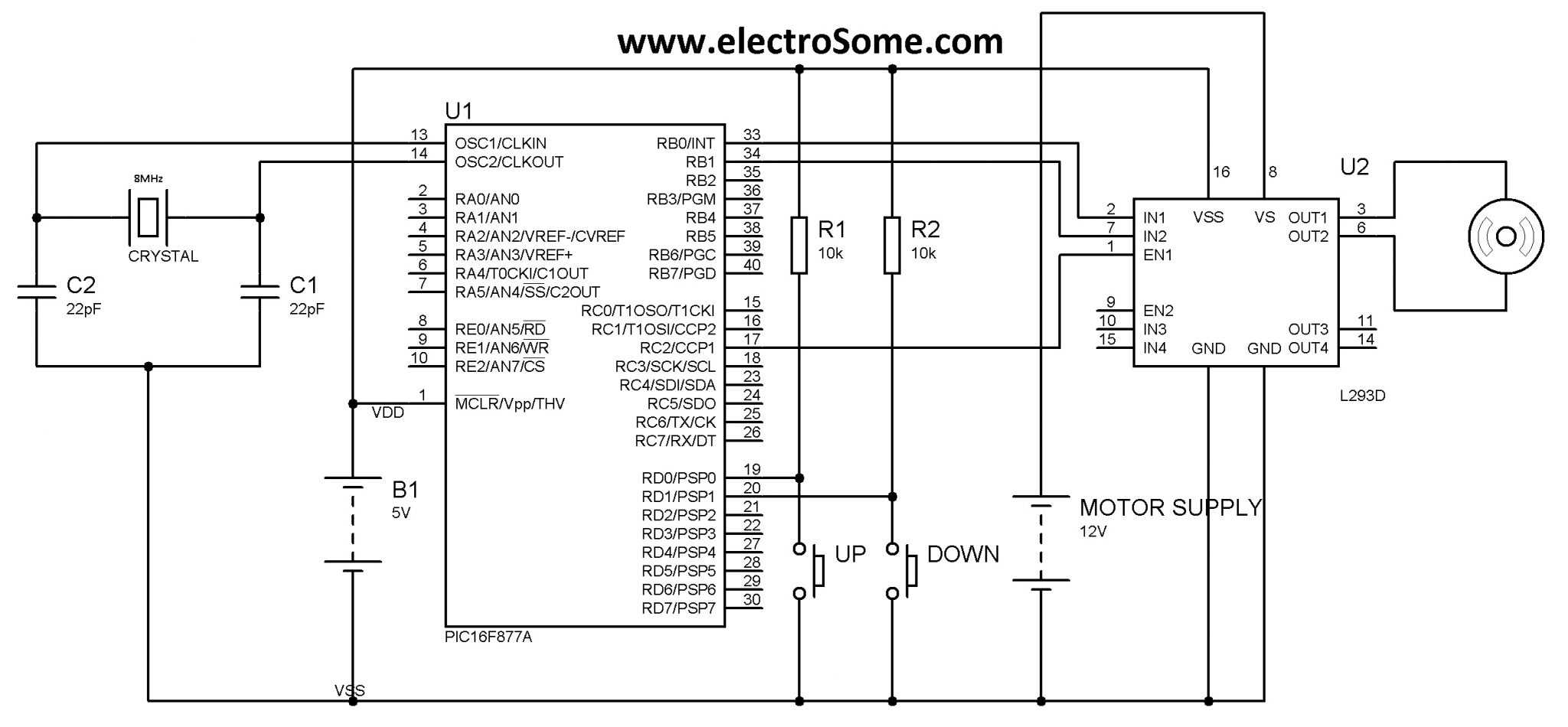
Note: VDD and VSS of the pic microcontroller is not shown in the circuit diagram. VDD should be connected to +5V and VSS to GND.
Two push button switches are connected to 1st and 2nd pins of PORTD which is used to control the duty ratio of the generated PWM. Pressing the UP switch increases the duty cycle, which increases the motor speed while pressing the DOWN switch decreases the duty cycle, which decreases the motor speed. Here we use CCP1 module of PIC 16F877A to generate PWM and it is given to the enable pin of L293D. The direction of rotation of motor can be control using the 1st and 2nd pins of PORTB.
MikroC Code
void main()
{
  short duty  = 0; //initial value for duty

  TRISD = 0xFF; //PORTD as input
  TRISC = 0x00; //PORTC as output
  TRISB = 0x00; //PORTB as output
  PORTB = 0x02; //Run motor in anticlock wise

  PWM1_Init(1000);  //Initialize PWM1
  PWM1_Start();  //start PWM1
  PWM1_Set_Duty(duty); //Set current duty for PWM1

  while (1)        // endless loop
  {
     if (!RD0_bit && duty<250) //if button on RD0 pressed
     {
        Delay_ms(40);
        duty = duty + 10;  //increment current_duty
        PWM1_Set_Duty(duty);  //Change the duty cycle
     }
     if (!RD1_bit && duty >0) //button on RD1 pressed
     {
       Delay_ms(40);
       duty = duty - 10;  //decrement duty
       PWM1_Set_Duty(duty);
     }
    Delay_ms(10);      // slow down change pace a little
  }
}
The parameter of PWM1_Set_Duty() is duty ratio which ranges from 0 to 255, ie 0 means 0% duty cycle and 255 means 100% duty cycle.
I think the program is self explanatory, so if you have doubts please comment below.
You can download the hex file, MikroC source code, Proteus files etc here…


You may refer this article : https://electrosome.com/pwm-pic-microcontroller-mplab-xc8/
Can you help me in getting the xc8 compiler code for this
How to check L293D whether working or not ? Easily ???
Why i can’t build that code u give? Have https://uploads.disquscdn.com/images/85614e6c35533503f42f9c3c67f9be37a2504f2d92944d5e02528a543c584e46.jpg error
hey sir about this post how to add another output ad IC Machine Drive?
Sorry, I don’t understand.
Kindly use our forums ( https://electrosome.com/forums/ ) for asking dobuts outside the scope of above article.
hi..in power factor correction how to calculate the time difference average.
hi..in power factor correction how to calculate the time difference average
Yes, you can use H bridge with mosfets.
If you want additional protection, you can add additional circuits for that.
There won’t be much changes since it is MikroC compiler.
Me I use Pic16F628A? What should I change in code?
This code is for MikroC pro compiler.
hi sir. can i know is this code program can use in pic c compiler. if cant how to change it
https://electrosome.com/pwm-pic-microcontroller-mplab-xc8/
sir , i hove a doubt about how to stop the dc motor? using pic 16f877a ..please send me souce code.
how to do in mplab?
Just invert the inputs to IN1 & IN2 of L293D.
how does one change direction?
ok got it, thanks sir
That will be showing animation with taking account of inertia. It should become constant after some time… after attaining maximum speed.
PWM is varying the average output voltage, so it controls the speed by changing voltage itself.
when I simulate this on proteus, on one fixed value of duty cycle the speed keeps on increasing. Infact it should remain constant for a a single value of duty cycle. You think is that a software draw back ?
the motor about which i am talking is a DC series wound motor which is used as starter motor in automobiles.these motors are powered by 12V dc supply by battery and what i know is that speed of dc motor depends on applied voltage and i think there is no other way than PWM by which speed of DC motor could be varied over a range. so please help me if i am wrong about this and would it be possible to control this type of motor by this method.
It actually depends on the type of motor you need to use.
What do you mean by that ? Motor speed should increase when you increase the duty cycle. If you need constant speed, don’t change duty cycle.
hello sir, i don’t know much about electronics as a mechanical engineer but i want to know, by this method described above can we control the speed of a heavy motor like 1.5kw to 2kw power capacity or there is any other way?
thanks in advance
When i increase the duty cycle the motor speed keeps on increasing how to make it constant ?
The micro C code plz….
Sorry, we don’t have any assembly codes.
Just connect a potentiometer to the ADC input of a microcontroller. As the input voltage varies, adc result will also vary. You can easily convert this to PWM.
Hello can i have the code for direction and speed control in assembly? Thank you
You can connect potentiometer to ADC input of microcontroller. Then vary the PWM depending on the A/D results.
How can i control DC motor speed using two potentiometer and op-amp with PIC Microcontroller??
Yes, you can use. Try the following link.
https://electrosome.com/pwm-pic-microcontroller-mplab-xc8/
NO, you cannot vary the speed of brush less dc motor by simply varying voltage.
hey,i just wan to know the is that coding can be use in mplab ide?
Is this the same for bldc motor???
Use this link for XC8.
https://electrosome.com/pwm-pic-microcontroller-mplab-xc8/
Check for the errors shown by the compiler.
If you want detailed help, please post it with complete code in our forums, https://electrosome.com/forums/
No header files or library files are required. It uses built in library of MikroC.
No, the above code is intended for MikroC only.
the coding is
#include
#include
#include”xc.h”
#include
#define byte unsigned char
void main()
{
short duty = 0; //initial value for duty
TRISD = 0xFF; //PORTD as input
TRISC = 0x00; //PORTC as output
TRISB = 0x00; //PORTB as output
PORTB = 0x02; //Run motor in anticlock wise
PWM1_Init(1000); //Initialize PWM1
PWM1_Start(); //start PWM1
PWM1_Set_Duty(duty); //Set current duty for PWM1
while (1) // endless loop
{
if (!RD0_bit && duty0) //button on RD1 pressed
{
__delay_ms(40);
duty = duty – 10; //decrement duty
PWM1_Set_Duty(duty);
}
__delay_ms(10); // slow down change pace a little
}
Hi, what are the header files and library files required for this?
Thanks
if i use ccs compiler my program is not dumping ..dont knw wats wrong with dat?
sir may i use 12v BLDC motor???have ccs compiler..may i use the code in mplab ide
Just change the PORT register to LAT for output write operations. …
hello can you write the code for pic18f4550
in xc8
You should use a GSM modem for that.
Hello, the above tutorial is for DC Motor.. not for Servo Motor…and you can’t use PWM module for controlling servo.
hey guys i need help to solve this question?
draw a circuit to Turn ’ON’ the ignition circuit when
the interior light is ‘OFF’ AND when your student number has been entered.
After 3 failed attempts at entering
the student number the required number will default to ‘25122015’.
Once ‘ON’ the ignition must stay
‘ON’ even if the interior light is switched ‘ON’
This must be simulated in Circuit
Wizard.
In above problem ………..by using 8051 Microcontoller?
Sir ..Good evening………..
How can we control the speed a DC motor by receiving a sms or alert signal
hey i used the foolowing code
unsigned int temp_res;
unsigned short temp_duty;
void main()
{
ADCON1 = 0x80; // Configure analog inputs and Vref
PORTC = 0;
TRISC = 0; //all PORTC pins output
// Initialize and start the PWM unit
PWM1_Init(5000);
PWM1_Start();
while(1){
temp_res = Adc_Read(0); // Get results of
AD conversion
//from channel
0 (RA0 pin)
temp_duty = (temp_res/4); // Convert the 10
bit value
//to 8 bits
PWM1_Set_Duty(temp_duty); // Set the duty
value
Delay_ms(20000); // Slow everything down a
little
}
}
the value of servo remains const at -90 degree .
its value is not changing with adc values
As you are using Servo Motor.. please read our servo motor tutorial..
https://electrosome.com/servo-motor-pic-microcontroller/
Just change the pulse width according to the adc value.
Just invert RB0 and RB1
hi ligo . i am using adxl 345 and using dc servo . i wish to know after the conversion of analog values from adxl by pic microcontroller 16f452 how will i give this digital value to pwm so that my motor rotaes proportionally with the adxl tilting.
thnx in advance
hye ligo..how to control motor speed and direction at same time using pic microcontroller..
Yes… torque will decrease… as the current decreases.
If you want to decrease speed without lossing speed, you should use proper gears ..
while using pwm the torque decreases , why?
What do you mean ?
what is pwm1_init for 20mhz frequenc
Sorry, I don’t understand your question. Can you please elaborate ?
sir i want to the circuit diagram of pic controller of 230v but above circuit only give 12v,i am want 230v so pls reply me
You can read it using a microcontroller.
If you need more support, please open a new topic in our forums (https://electrosome.com/forums)
Sorry we haven’t yet that project..
sir,
And need the circuit diagram of automatic railway gate on/off controller .If u having please send me
sir, may I know how the unique code is generated from an ir sensor when it sense the ir remote pulse. and how can we get the codes…….?
can u help us…..
sir,
whether we can control the same ckt with remote.
if you having any circuit diagram means please mail me.
Sorry, we don’t have assembly language programs..
dear sir,
whethere i can control the motor speed with IR remote
sir i want program in assemly language in pic16f877
Do like this :
if(button1 pressed)
{
PORTB.F0 = 1;
PORTB.F1 = 0;
}
if(button 2 pressed)
{
PORTB.F0 = 0;
PORTB.F0 = 1;
}
i want to know how to control the direction of motor using push button,which means it have forward button and reverse button.thank you
http://electrosome.com/stepper-motor-pic-microcontroller/
my email : [email protected]
sir i want to use two stepper motors. i am using a3967 driver kit so i need to controlled them step by step in horizontal and vertical manner as i am building a xy scanner so suggest me some help for it
Hi Mr. Ligo. do u have whatsapp or Facebook? I want talk with u in privacy.. I need your help, sir. Please email ur personal contact at [email protected]
i really need ur help..
hey Ligo, can you tell me the rating of the motors for which this cct is applicable? and is it verified in terms of hardware ???…..
PORTB = 0x02; //Run motor in anticlock wise
0x02 = 0b00000010
Sir, Here the pwm signals are being generated but in which part of the code are we sending them to Inputs of L293D (RB10 and RB11) ??
No, L293D is able to handle only 600mA continuous current and 1.2A Peak current.
You can use power transistors.
hii , can i use a 12v/ 2 amp dc motor here
Hello,
The above code is written for MikroC PRO Compiler..
were is my mistake???
xc8.exe –pass1 –errformat=”Error at file %%f line %%l column %%c: (%%n) %%s” –warnformat=”Warning at file %%f line %%l column %%c: (%%n) %%s” –msgformat=”Message at file %%f line %%l column %%c: (%%n) %%s” -G –chip=16F877A -O”main.p1″ “../main.c”
Microchip MPLAB XC8 C Compiler (Free Mode) V1.31
Copyright (C) 2014 Microchip Technology Inc.
License type: Node Configuration
Warning at file line column : (1273) Omniscient Code Generation not available in Free mode
Warning at file ../main.c line 15 column 1: (361) function declared implicit int
Warning at file ../main.c line 16 column 1: (361) function declared implicit int
(908) exit status = 1
make: *** [main.p1] Error 1
Warning at file ../main.c line 17 column 1: (361) function declared implicit int
Error at file ../main.c line 21 column 18: (195) expression syntax
Error at file ../main.c line 23 column 13: (194) “)” expected
Error at file ../main.c line 27 column 18: (195) expression syntax
Error at file ../main.c line 29 column 13: (194) “)” expected
Error at file ../main.c line 33 column 10: (194) “)” expected
Error at file ../main.c line 34 column 1: (285) no identifier in declaration
Warning at file ../main.c line 34 column 1: (374) missing basic type; int assumed
Error at file ../main.c line 34 column 1: (314) “;” expected
Error at file ../main.c line 35 column 1: (285) no identifier in declaration
Warning at file ../main.c line 35 column 1: (374) missing basic type; int assumed
Error at file ../main.c line 35 column 1: (314) “;” expected
Error code 2
how to do if i want to control the speed by using 5 switches
means that i have 5 speed. (just like fan)
This wish is reversible reversible how dear?, You can edit the code to help me please? Thank you
Hi Mate, I want to use this for a robotic arm, I am planing to use 2 DC motors for 2 joints (Each motor for each joints). I decided to use L293 motor driver full bridge IC. My question is should I use two L293 IC for 2 motors? both joints moves up and down wards. not side movement.
I am designing my own PCB board on Altium designer. so plzz give me clear full circuit the with PIC16f877A and L193 for 2 motors. Thank you and have a nice day
sir ,
i want to make a temperature controlled fan using pic168f77a i connected a temperature sensor in to pic’s adc input port A0.. and tried with your above program with slight modification.. but it shows error . it shows we want to initialise the identifier TRISD,C,B.. and lot of other errors..
can you please help me..?
hi i am doing project on people counting system and home automation so as number of people increase temperature increase it is necessary and if yes so i can control the speed by pwm ? i am mot using temperature sensor. thanks
hello iwant to control dc motor and feed back to micro controller by using vco ineed the program in micro c
is it possible to run a 3V DC motor directly from the microcontroller? or do i need a motor driver for it to turn?
Use google .. There are a lot of tutorials over internet..
But i don’t know how to write code with Mikro Basic to apply to my line follower.
You can use PWM to control the speed of motors… depending upon the curves..
I have one project about line follower. Can you give me some information about it???
Please refer the datasheet of your microcontroller..
How to use this with a PIC32, what ports to use ?
Hello, it will work..
Did you tried it in hardware..??
If it is not working in hardware.. try connecting the EN1 pin to VDD and check whether the motor is working……..
if it works.. then reconnect it to ccp pin… then try reducing the pwm frequency…
the above circuit not working, i tried many times, pls help me….
You can use the PWM Method,… but can’t use L293D…. ..
You should use appropriate drivers…
is the above method suitable to control the speed of a 36v 360 watt dc motor?
The above microcontroller have ADC…. I think the above microcontroller is enough for you… since I think you are dealing with slowly varying analog signals…………..
A driver is required.. to drive the motor..
two questions
1) Can this setup receive an analog signal to the microcontroller? does it have ADC? Basically what type of micro controller is used to monitor an analog signal in real time and compute the motor speed based on a function of the incoming analog signal? (or would a DSP be more suited for this)
2)is it always necessary to have a motor driver between the microcontroller and the motor? Or are do there exist microcontrollers that can directly control the motor speed?
To adjust the speed of stepper motor, you should control the delay between stepping..
PWM to control stepper motor is it possible
It can be used in robotics applications…….
PLEASE GIVE ME THE FUTURE USE AND APPS OF
SPEED
CONTROL OF A DC MOTOR USING MICROCONTROLLER 8051
Sure,,, give the output of DTMF decoder to input of PIC and write the required code to control the motor..
My input is form the dtmf decoder, can i use this code to control my DC motors?
Why don’t you refer its datasheet??
There are 4 PWM channels in Atmega16… there is no CCP…
does a atmega16 microcontroller have a CCP?
Thank you so much!
To display speed in rpm you need more than one seven segment.. You can use above link and Hex() covert a number to its 7 segment code…
The speed of the dc motor can be find using an IR transmitter and Receiver, by counting the no. of times IR beam is cutting in a minute…….
okay, thanks! And what about the coding part ? If i want to display the speed in rpm
If you need to connect only one 7 segment, simply connect its 7 inputs to any of the output pins of the microcontroller. If you need to connect more than one 7 segments… try this article. It might help you..
http://www.electrosome.com/multiplexing-seven-segment-displays/
what’s the purpose of using the crystal?
Yes.. of course… .. Note that for 18f series.. output register is LAT… not PORT… PORT is used for reading data……You need to change the output registers of above program as LAT… no other changes in program..
For the speed control of 3 phase induction motor you need 3 pwm channel.. but the above pic has only two.. but you can generate a Software generated pwm using interrupts of CCP module……
You need to vary the frequency of the pwm to control the speed of three phase induction motor..
what about 3ph induction motor i wanna connect potentiometer with pic to controlled motor speed i need pic code of this case any one help me
can we i use this program for pic 18f4520 to control the speed of 12v dc motor??
Sorry, I haven’t yet used pic assembly language…
Hey great documents, thanks. Sir, I need to do a pic16f84a project that controls dc motor gonna use mosfet, i need to speed it up and slow it down with a pwm technique can you help me with circuit and assm code if you have some time?
Yes you can generate continuous pwm by changing dutycycle…
The parameter of PWM1_Set_Duty() is duty ratio which ranges from 0 to 255, ie 0 means 0% duty cycle and 255 means 100% duty cycle.
I want to generate continuous pwm on the basis of voltage. Can it possible that one pin generate pwm continuously while my program observing voltage continuously with out disturbing PWM. IN this program you add 10 in duty cycle how much duty it increase.Thanks
You need to change only the crystal frequency in the project settings…
Can i use crystal 20mhz and 18pf capacitor? And what should i change in the coding?
Nop, change the Clock Frequency in the project settings..
hi,
I am using a pic18f452 with a crystal 4Mhz …. Do i have to change the constant 1000 ???
Nop, since we are using MikroC compiler, there are only some modifications… To set direction of io pins use TRIS register, to read data from io pins use PORT register but for write data to io pins use LAT register…
In the above program change PORT register to LAT, it will work..
i have a problem here. I’m using PIC 18F4550. Is it requires a totally different code?
Sorry, I haven’t yet used pic assembly language ..
can you please help me to right the above program in assembly language plzzz
Use a 3 phase brushless motor instead of dc brushless motor…. and control its speed using 3 pwm…………
am trying 2 run it with pwm from pic16f887 but it keeps implying that somrthing is wrong with my signal ,.. so am thinking of substituting the ESC with a motor driver IC .. good idea or not ?
Brushless DC Motors uses a 3 phase AC motor that has connected to a Electronic Speed Controller (ESC) circuit…. so there is no use of DC PWM controller in this case……..
can i use this setup to drive brushless outrunner motors ?
i have tries using ESC with very little luck
thank you !
Yes, of course…………. You can generate appropriate pwm for your applications.. This is just a tutorial for getting started with PWM
Hi..I had a doubt that rather than using switch to control duty cycle is it possible for us to write a code and accordingly generate pwm?
Yes, it may be said like that as the motor is not fully ON or OFF …. …. You can incorporate fuzzy logic concept in to above code, for eg: speed control of FAN according to the room temperature…
thank u so much..is there a fuzzy logic concept in the above code or can we incorporate the fuzzy logic concept into the above code.?
You can use the above program for pic 18f452 with some modifications. As shown above TRIS registers are used to set the direction of a pin while to write a data to a output pin LAT register is used. But for reading a port PORT register is used as above………. You can use the above functions in mikroc for 18f452
HI…ur posts are very useful and informative…i was wondering if you could provide me with the details of doing this same task with a pic18f452.