

Interfacing DS18B20 Temperature sensor with Raspberry Pi
Contents
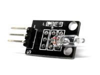
DS18B20 is a commonly used temperature temperature sensor providing 9 bit to 12 bit digital Celsius temperature measurements. The sensor communicates over one wire bus. Each sensor has a 64 bit serial code enabling multiple sensors to be connected to the same one wire bus.
The Raspberry Pi has drivers for one wired devices to be connected to GPIO pin-4 by default. 1-wire is a device communication data bus system developed by Dallas semiconductor providing low speed data, signalling and power over a single signal wire. One wire is similar to I2C with longer range and low data rates. It can be used to communicate with inexpensive devices like thermometers, humidity sensors and other one wire sensors over a long range. The main advantage is since each device has a unique address, any number of devices can be connected on a single wire limited by the drive capacity of Raspberry Pi’s GPIO and the total capacitance seen on the line.
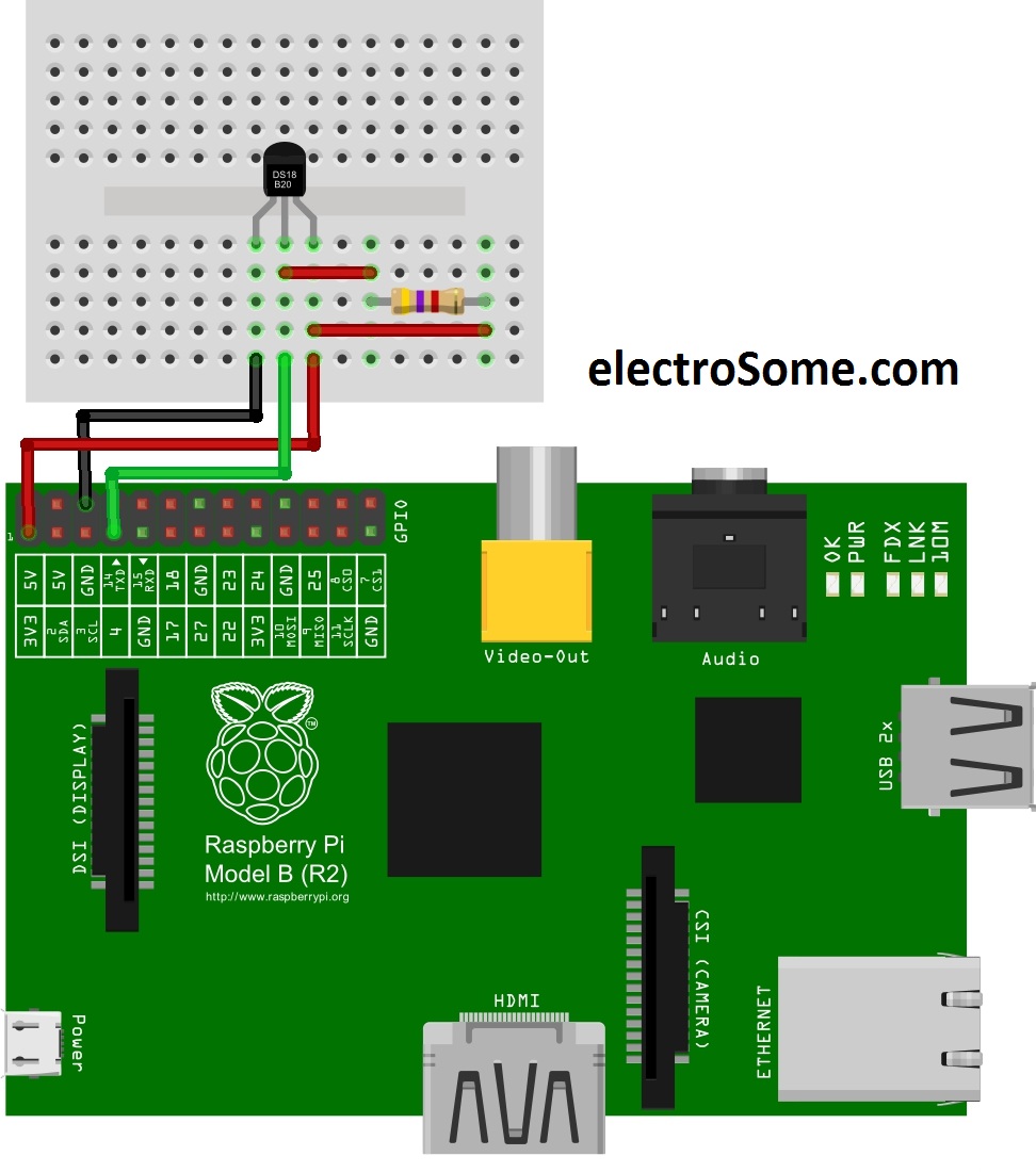
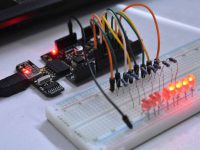
Circuit Diagram
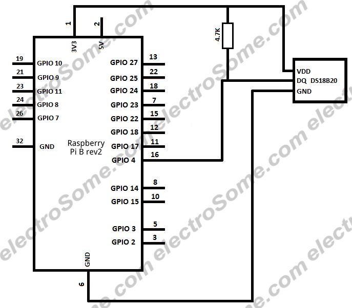
The one wire bus requires a weak pull up resistor as all devices linked to this bus via a tri-state or open drain output. Here a 4.7KΩ resistor is used as pull up.
Sensor not detecting after OS update
Users having Rasbian with updated Linux kernel 3.18 need to edit boot config file to work with one wire sensors.
- In terminal edit config file,
sudo nano /boot/config.txt - And add,
dtoverlay=w1-gpio,gpiopin=4 - And save (Ctrl+X)
Reading temperature using Terminal
The one wire communication device kernel modules can be loaded by typing,
sudo modprobe w1-gpio
sudo modprobe w1-therm
Point to the address of the temperature sensor,
cd /sys/bus/w1/devices/28*
Note: If more than one device is connected use cd /sys/bus/w1/devices/ and ls to list all the devices and cd address where address is the unique address of the device required. For eg.cd 28-00042d8165ff
Display temperature,
cat w1_slave
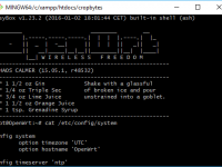
Terminal Output
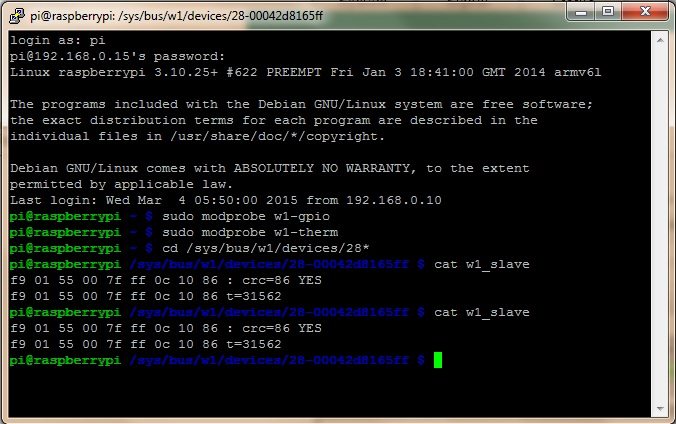
The displayed data consist of two lines – first line representing the value read and CRC check and second line temperature in Celsius x 1000.
This can also be done in Python with python handling CRC errors and the temperature displayed both in Celsius and Fahrenheit.
Python code
import os                                                  # import os module
import glob                                                # import glob module
import time                                                # import time module
os.system('modprobe w1-gpio')                              # load one wire communication device kernel modules
os.system('modprobe w1-therm')
base_dir = '/sys/bus/w1/devices/'                          # point to the address
device_folder = glob.glob(base_dir + '28*')[0]             # find device with address starting from 28*
device_file = device_folder + '/w1_slave'                  # store the details
def read_temp_raw():
   f = open(device_file, 'r')
   lines = f.readlines()                                   # read the device details
   f.close()
   return lines

def read_temp():
   lines = read_temp_raw()
   while lines[0].strip()[-3:] != 'YES':                   # ignore first line
      time.sleep(0.2)
      lines = read_temp_raw()
   equals_pos = lines[1].find('t=')                        # find temperature in the details
   if equals_pos != -1:
      temp_string = lines[1][equals_pos+2:]
      temp_c = float(temp_string) / 1000.0                 # convert to Celsius
      temp_f = temp_c * 9.0 / 5.0 + 32.0                   # convert to Fahrenheit
      return temp_c, temp_f

while True:
   print(read_temp())                                      # Print temperature
   time.sleep(1)
Output
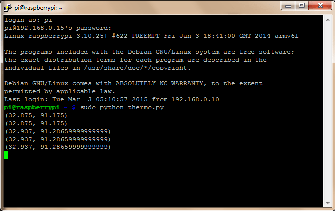
The python output consists of temperature in both Celsius and Fahrenheit scale displayed at an interval of one second.
Any doubts or suggestions? Comment below.


pi@raspberrypi:~ $ sudo modprobe w1-therm
pi@raspberrypi:~ $ sudo modprobe w1-gpio
pi@raspberrypi:~ $ cd /sys/bus/w1/devices
pi@raspberrypi:/sys/bus/w1/devices $ ls
pi@raspberrypi:/sys/bus/w1/devices $
I didn’t getting cd address such as cd 28-xxxxxxxxxxxxx please help me…
plz give me replay fast
I am getting error with this code( device_folder = glob.glob(base_dir + ’28*’)[0] # find device with address starting from 28*
IndexError: list index out of range)this is the error
I am error with this code which is index( device_folder = glob.glob(base_dir + ’28*’)[0] # find device with address starting from 28*
IndexError: list index out of range) this is the error I am getting.
https://uploads.disquscdn.com/images/f4193951a173334c45bb39c18e82361f9b956deaaa05fdfbae9b457fb5e043e9.jpg I am also facing same problem. can anyone help
i got same error. did you find the solution?
i am get this error :
modprobe: FATAL: Module w1–gpio not found.
after installing sudo modprobe w1-gpio and sudo modprobe w1-therm i am not able to get a unique address of the sensor ie. cd /sys/bus/w1/devices/28* what can i do?? i am using raspberry pi 3 B v 1.2
i could able to see two address from 20* and followed by 0s and one wl-master directories. pls do help me with this
We are not feeding 5V to Rpi GPIO pins. 5V in the block diagram is output not for providing input.
In Block Diagram u used 3.3v ….
I read somewhere that raspberry pi GPIO pins will burn if we directly feed 5v!
It is 5V output pin…
Can i connect +5v that is pin2 of raspberry pi instead of 3.3v
hello
please help me i have problem in my project
i would to show a value of puissance and energy but i don’t find a correct value
please help me if you can:
code:
// LCD module connections
sbit LCD_RS at RB5_bit;
sbit LCD_EN at RB7_bit;
sbit LCD_D4 at RC4_bit;
sbit LCD_D5 at RC5_bit;
sbit LCD_D6 at RC6_bit;
sbit LCD_D7 at RC7_bit;
sbit LCD_RS_Direction at TRISB5_bit;
sbit LCD_EN_Direction at TRISB7_bit;
sbit LCD_D4_Direction at TRISC4_bit;
sbit LCD_D5_Direction at TRISC5_bit;
sbit LCD_D6_Direction at TRISC6_bit;
sbit LCD_D7_Direction at TRISC7_bit;
// End LCD module connections
char look(int a)
{
switch(a)
{
case 0:
return ‘0’;
case 1:
return ‘1’;
case 2:
return ‘2’;
case 3:
return ‘3’;
case 4:
return ‘4’;
case 5:
return ‘5’;
case 6:
return ‘6’;
case 7:
return ‘7’;
case 8:
return ‘8’;
case 9:
return ‘9’;
default:
return ‘.’;
}
}
void main () {
int value ;
char value1 [13];
unsigned int v,vp,ip,i,w,E;
char *volt = “00.0”;
char *current = “0.00”;
char *watt=”00.0″;
char *ENRG=”00.0″;
int t ;
TRISA = 0xFF;
TRISB=0x00;
TRISD.f7=0x00;
Lcd_Init();
Lcd_Cmd(_LCD_CLEAR);
Lcd_Cmd(_LCD_CURSOR_OFF);
while(1)
{
ADCON1 = 0x00;
value=adc_read(0);
v = ADC_Read(2);
i = ADC_Read(3);
i = (i*4.89)/0.47;
v = ((v*4.89)/20)*120;
value=value*0.488;
floattostr(value,value1);
if(v!=vp || i!=ip )
Lcd_Cmd(_LCD_CLEAR);
vp = v;
ip = i;
volt[0] = look(v/10000);
volt[1] = look((v/1000)%10);
volt[3] = look((v/100)%10);
Lcd_Out(1,1,”Voltage = “);
Lcd_Out(1,11,volt);
Lcd_Out(1,16,”V”);
current[0] = look(i/1000);
current[2] = look((i/100)%10);
current[3] = look((i/10)%10);
Lcd_Out(2,1,”Current = “);
Lcd_Out(2,11,current);
Lcd_Out(2,16,”A”);
Delay_ms(250);
Lcd_Cmd(_LCD_CLEAR);
w=(ip*vp);
watt[0] = look(w/10000);
watt[1] = look((w/100)%10);
watt[3] = look((w/10)%10);
Lcd_Out(2,1,”puissance=”);
Lcd_Out(2,11,watt);
Lcd_Out(2,15,”W”);
delay_ms(500);
Lcd_Cmd(_LCD_CLEAR);
t=2;
E=w*t;
ENRG[0] = look(E/10000);
ENRG[1] = look((E/100)%10);
ENRG[3] = look((E/10)%10);
Lcd_Out(1,1,”ENERGIE = “);
Lcd_Out(1,11,ENRG);
Lcd_Out(1,16,”J”);
Delay_ms(250);
if (value > 18)
{PORTd.f7=1;
delay_ms(20000);}
if(value < 18 )
{PORTd.f7=0;
delay_ms(20000);}
}
}