

Interfacing Real Time Clock (RTC) DS1307 with PIC Microcontroller
Contents
 DS1307 is a low power serial real time clock with full binary coded decimal (BCD) clock/calendar plus 56 bytes of NV SRAM (Non Volatile Static Random Access Memory). Data and Address are transferred serially through a bidirectional I2C bus. The RTC provides year, month, date, hour, minute and second information. The end date of months is automatically adjusted for months fewer than 31 days including leap year compensation up to year 2100. It can operate either in 24-hour format or 12-hour format with AM/PM indicator. DS1307 comes with built-in power sensing circuit which senses power failures and automatically switches to back up supply. The DS1307 RTC uses an external 32.768kHz Crystal Oscillator and it does not requires any external resistors or capacitors to operate.
What is I2C (I²C) ?
I²C (Read as “i-squared cee”; Inter-Integrated Circuit) is a multi-master serial single-ended computer bus invented by Philips, used to attach low-speed peripherals to a embedded system,cellphone, motherboard, or other electronic device and is generally referred to as “two-wire interface”. It consists of two wires called SCL and SDA. SCL is the clock line which is used to synchronise all the data transfers through I2C bus and SDA is the data line. It also need a third line as reference line (ground or 0 volt). A 5v power should be also be given to the device for its working. The main thing to be noted is that both SCL and SDA are Open Drain drives. Which means that the chip can drive its low output but can’t drive high output. Thus we must provide two pull up resistors to 5v for SCL and SDA, to make it to drive high output as shown in the fig.

Selection of Pull Up Resistors
1. The rise time of SCL and SDA voltages will depend up on the value of pull up resistor and I2C bus capacitance. Thus pull up resistor should be selected according to the I2C bus frequency being used.
2. The higher value of pull up resistor is limited by the rise time and the lower vale of pull up resistor is limited by the drive strength (IOL max) of the SDA and SCL drivers. If the pull up resistor is very low , the SCL and SDA outputs might not be establish enough low voltage.
I recommend you to use 1.8K pull up resistors.
MikroC PRO for PIC Microcontroller provide built-in libraries for I2C devices. DS1307 works as a slave device on I2C bus. Register access can be obtained by implementing a START and followed by device identification address. Then each registers can be accessed sequentially by using its address until a STOP condition is executed.
Device Address : 0X68 = 1101000
Reading Data from DS1307
MikroC Code
unsigned short read_ds1307(unsigned short address)
 {
   unsigned short temp
   I2C1_Start();
   I2C1_Wr(0xD0);
   I2C1_Wr(address);
   I2C1_Repeated_Start();
   I2C1_Wr(0xD1);
   temp = I2C1_Rd(0);
   I2C1_Stop();
   return(temp);
 }
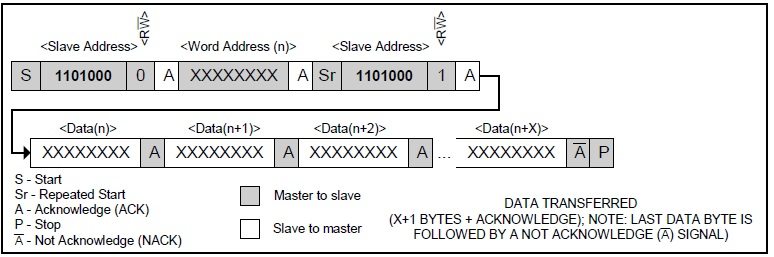
I2C1_Start() check whether the I2C bus is free and issues start signal. I2C1_Wr() sends data bytes through the I2C bus. We first send address bit (address 0X68 + direction bit (0 for write, 1 for read) 0x68 followed by 0 –> 0xD0). Then we select the required Time keeper register using its address (0 – Seconds, 1 – Minute, 2- Hour etc) to read data. In these operations data is send from PIC to RTC. Address of Time keeper registers can be find from the following table.

I2C1_Repeated_Start() will provide repeated start signal for reading the data, since data transfer takes place from RTC to PIC. Then we read the data of the selected register using I2C1_Rd(0) (if the parameter is given as 0, it will not sends acknowledge signal). Then STOP signal is issued by using I2C1_Stop().

Writing Data to DS1307
MikroC Code
void write_ds1307(unsigned short address, unsigned short w_data)
 {
   I2C1_Start();
   I2C1_Wr(0xD0);
   I2C1_Wr(address);
   I2C1_Wr(w_data);
   I2C1_Stop();
 }

Writing Data from DS1307 is smiler to reading data from it. After selecting the required register for writing data, the data to be written is send using the I2C1_Wr().
I already mentioned that DS1307 RTC can be run either in 12-hour mode or 24-hour mode. See the Time Keeper Registers Table, Bit 6 of Hour register is defined as the 24-hour or 12-hour mode selection bit. When this bit is made high, 12-hour mode is selected and Bit 5 will represent AM/PM (Logic High represents PM). When Bit 6 is made low, 24-hour mode will be selected and Bit 5 will be used for representing Hour.
Note: Hours Value must be re-entered when the Hour mode is changed.


Hi,
What do you meant by sheet paper ?
Thanks everything is working correctly sir.
Can you please send me sheet paper of this work ?
Try adjusting contrast of the LCD also make sure that LCD connections are correct and PIC is running the program.
LCD didnt show any thing sir
Hi they sir Ligo George!! your code was awesome :)) I would like to ask if this code can use in PIC16F887 using same code or need to modify??
I do my project in mplab xc8 t interface RTC with PIC 16F877A .The thing is how to change the time format to 12 hrs.I dont know where to change the register value .I have also red through all data sheet .is say that to set 6th bit but i dont know where to change
i am using IN1307 RTC ic. It work properly but suddenly crystal is not working.
What is the problem in my hardware.
Try this link for XC8 I2C libraries. : https://electrosome.com/i2c-pic-microcontroller-mplab-xc8/
This tutorial written in MikroC. If you aren’t familiar with programming, can be difficult to implement this MikroC source code in XC8. The matching I2C commands you can find in the i2c.h header file, located in Program FilesMicrochipxc8v1.34includeplib (this example is in case of XC8 version of 1.34)
hey,
I am facing a problem.
i am using mplabX compiler-xc8.
pullups 4.7k
please help.
where are the functions I2C1_Start(); I2C1_Wr(); etc defined??
char seconds ; minutes ; hours ; ANSEL ; ANSELH ; TRISD ; PORTD;
sbit Soft_I2C_Scl at RC3_bit;
sbit Soft_I2C_Sda at RC4_bit;
sbit Soft_I2C_Scl_Direction at TRISC3_bit;
sbit Soft_I2C_Sda_Direction at TRISC4_bit;
sbit LCD_RS at RB3_bit; // LCD module connections
sbit LCD_EN at RB2_bit;
sbit LCD_D4 at RB4_bit;
sbit LCD_D5 at RB5_bit;
sbit LCD_D6 at RB6_bit;
sbit LCD_D7 at RB7_bit;
sbit LCD_RS_Direction at TRISB3_bit;
sbit LCD_EN_Direction at TRISB2_bit;
sbit LCD_D4_Direction at TRISB4_bit;
sbit LCD_D5_Direction at TRISB5_bit;
sbit LCD_D6_Direction at TRISB6_bit;
sbit LCD_D7_Direction at TRISB7_bit; // End LCD module connections
unsigned short read_ds1307(unsigned short address){
unsigned short r_data;
I2C1_Start();
I2C1_Wr(0xD0); //address 0x68 followed by direction bit (0 for write, 1 for read) 0x68 followed by 0 –> 0xD0
I2C1_Wr(address);
I2C1_Repeated_Start();
I2C1_Wr(0xD1); //0x68 followed by 1 –> 0xD1
r_data=I2C1_Rd(0);
I2C1_Stop();
return(r_data);
}
void write_ds1307(unsigned short address,unsigned short w_data)
{
ANSEL = 0; // Configure AN pins as digital I/O
ANSELH = 0;
PORTB = 0;
TRISB = 0; // Configure PORTB as output
I2C1_Init(100000); // initialize I2C communication
I2C1_Start(); // issue I2C start signal
I2C1_Wr(0xA2); // send byte via I2C (device address + W)
I2C1_Wr(2); // send byte (address of DS1307 location)
I2C1_Wr(0xAA); // send data (data to be written)
I2C1_Stop(); // issue I2C stop signal
}
unsigned char BCD2UpperCh(unsigned char bcd)
{
return ((bcd >> 4) + ‘0’);
}
unsigned char BCD2LowerCh(unsigned char bcd)
{
return ((bcd & 0x0F) + ‘0’);
}
int Binary2BCD(int a)
{
int t1, t2;
t1 = a%10;
t1 = t1 & 0x0F;
a = a/10;
t2 = a%10;
t2 = 0x0F & t2;
t2 = t2 <> 4;
t = 0x0F & t;
r = t*10 + r;
return r;
}
int second;
int minute;
int hour;
int hr;
int ap;
unsigned short set_count = 0;
short set;
char time[] = “00:00:00 PM”;
void main()
{
I2C1_Init(100000); //DS1307 I2C is running at 100KHz
ADCON1 = 0x06; // To turn off analog to digital converters
TRISA = 0x07;
PORTA = 0x00;
Lcd_Init(); // Initialize LCD
Lcd_Cmd(_LCD_CLEAR); // Clear display
Lcd_out(1,1,”Time:”);
do
{
set = 0;
if(PORTA.F0 == 0)
{
Delay_ms(1000);
if(PORTA.F0 == 0)
{
set_count++;
if(set_count >= 7)
{
set_count = 0;
}
}
}
if(set_count)
{
if(PORTA.F1 == 0)
{
Delay_ms(100);
if(PORTA.F1 == 0)
set = 1;
}
if(PORTA.F2 == 0)
{
Delay_ms(100);
if(PORTA.F2 == 0)
set = -1;
}
if(set_count && set)
{
switch(set_count)
{
case 1:
hour = BCD2Binary(hour);
hour = hour + set;
hour = Binary2BCD(hour);
if((hour & 0x1F) >= 0x13)
{
hour = hour & 0b11100001;
hour = hour ^ 0x20;
}
else if((hour & 0x1F) = 60)
minute = 0;
if(minute < 0)
minute = 59;
minute = Binary2BCD(minute);
write_ds1307(1, minute); //write min
break;
case 3:
if(abs(set))
write_ds1307(0,0×00); //Reset second to 0 sec. and start Oscillator
break;
}
}
}
second = read_ds1307(0);
minute = read_ds1307(1);
hour = read_ds1307(2);
hr = hour & 0b00011111;
ap = hour & 0b00100000;
time[0] = BCD2UpperCh(hr);
time[1] = BCD2LowerCh(hr);
time[3] = BCD2UpperCh(minute);
time[4] = BCD2LowerCh(minute);
time[6] = BCD2UpperCh(second);
time[7] = BCD2LowerCh(second);
if(ap)
{
time[9] = 'P';
time[10] = 'M';
}
else
{
time[9] = 'A';
time[10] = 'M';
}
Lcd_out(1, 6, time);
Delay_ms(100);
}while(1);
}
I think the above project is in 12 hour mode.
sir,
i made this project its working fine but the clock reset automatically after 15:59pm to 00:00am.
kindly suggest
Thank you
You can use if else statements for comparing… like. . if(HOUR > 6)
Dear Ligo George
Your explanations are awesome r u a teacher ?
Please give a simple comparison of hour to enable a output in RTC
i need only time to control a pin only ,In digital clock,contain LCD display.Can u provide a small program for pin control using RTC in Mikroc
Just compare the hour, minute values and control it. Nothing special.
How to enable a pin or relay based on 12 hr using RTC?
What is the error ??
for interfacing > i only wrote a code to read & display second using pic16f877a , sir …
where is my problem sir ?
//////////////////////////////////////////////////code/////////////////////////////////////////////////
// LCD module connections
sbit LCD_RS at RB4_bit;
sbit LCD_EN at RB5_bit;
sbit LCD_D4 at RB0_bit;
sbit LCD_D5 at RB1_bit;
sbit LCD_D6 at RB2_bit;
sbit LCD_D7 at RB3_bit;
sbit LCD_RS_Direction at TRISB4_bit;
sbit LCD_EN_Direction at TRISB5_bit;
sbit LCD_D4_Direction at TRISB0_bit;
sbit LCD_D5_Direction at TRISB1_bit;
sbit LCD_D6_Direction at TRISB2_bit;
sbit LCD_D7_Direction at TRISB3_bit;
// End LCD module connections
unsigned short read_ds1307(unsigned short address)
{
unsigned short r_data;
I2C1_Start();
I2C1_Wr(0xD0);
I2C1_Wr(address);
I2C1_Repeated_Start();
I2C1_Wr(0xD1);
r_data=I2C1_Rd(0);
I2C1_Stop();
return(r_data);
}
unsigned char BCD2UpperCh(unsigned char bcd)
{
return ((bcd >> 4) + ‘0’);
}
unsigned char BCD2LowerCh(unsigned char bcd)
{
return ((bcd & 0x0F) + ‘0’);
}
int second;
char textsec[]=”00″;
void main() {
CMCON = 0x07; // To turn off comparators
ADCON1 = 0x06; // To turn off analog to digital converters
i2c1_init(100000);
lcd_init();
lcd_cmd(_lcd_clear);
lcd_cmd(_lcd_cursor_off);
while(1){
second=read_ds1307(0); // 0 for second reg.
textsec[0] = BCD2UpperCh(second);
textsec[1] = BCD2LowerCh(second);
lcd_out(2,1,textsec);
}
}
Please use our forums (https://electrosome.com/forums) for asking doubts not related to above article.
HI, I wrote a assembly program for I2C connection with pic16f877a and ds1307, the code is working perfectly in the proteus simulation but its not working in hardware, can you tell what i have to do in the hardware set up?
actual cost for this project
Sorry, I haven’t.
ok bro,i mean to ask you, do you know a programmer code for doing real time clock without using a RTC…i mean i just want to use PIC 18F4550 and a LCD display only to do…..
I don’t get your question, the above article is about interfacing RTC.
Hello, I don’t get your question. Above article is about interfacing RTC.
bro what if say im not using RTC,jez use PIC & LCD what will be the programmer code
bro what if say i dont want to use RTC, what will be the programmer code..
pls reply me soon bro…im having an assingment to be submit on monday…
thank you for your kindness….
thank you bro..
I hope that you can use the above codes for 18F4550 without any change.
bro how to write a code for pic 18F4550 for digital clock using pic microcontroller…can you give me the code pls…
bro how to write a code for pic 18F4550 for digital clock using pic microcontroller…can you give me the code pls…
sir, while simulation it gets stuck.. what can be the reason………
how to get data and send it to serial port?
How to set 6-th bit on high for 24-hr mode in mikro c code ?
Dear Ligo, I have a certain application in which I need to turn a relay on then off for only 1 sec everyday at exactly 12AM….do you think that this RTC is suitable for such a simple application? or is there a cheaper solution?
Go to this page: http://www.electrosome.com/digital-clock-pic-microcontroller-ds1307/
there you can download program for digital clock…
The programming is done by using MikroC PRO
SIR,I MAKE THIS BY PIC CONTROLLER…FIRSTLY I CONNECT PIN OF DS1307 OF SCL AND SDL ON PIC CONTROLLER…BUT TELL HOW I PROGRAM MY PIC CONTROLLER ITS START WAORKING MY HARDWARE CIRCUIT IS COMPLETE BUT WANT PROGRAM TO START….IF PROGRAM IS ON BASIC ITS VERY HELPFUL TO ME…
Just change the lcd and place 7 segment displays…
You may use multiplexed 7 segment displays or use 4511 seven segment decoder. This link may help you..
http://www.electrosome.com/multiplexing-seven-segment-displays/
sir
Sir i want to make clock and clander on 7 segment so what changing have to do ??
ok sir! Thanks
10K is very large, reduce its value….
Try a value around 2K, eg: 1.8K..
Yeah I have connected 10K of resistor each for SCL and SDA but between SDA and SCL resistor has to be attached then it shows time! I knew its not recommended to add resistor between SCL and SDA but without LCD shows”Time:??????” ! so what might be the reason?
1K Resistor between SCL and SDA???
You should connect 2 resistors from SCL and SDA to Vcc.
The value of the resistors affect the I2C communication. The resistance value depends on the speed of the I2C communication.
Sir some strange situation I have faced in our project of digital clock, I have attached a 1K resistor between SCL and SDA .Then the time was shown on LCD or else it showed only question marks… and when I attached a resistor between SCL and SDA then it started showing time. Isn’t it strange? or is there any other reason…
At the time of first application of power it will show date 01/01/00 and time 00:00:80 (time will not run) ……. then you need to set second ………….then the will start running…
Sir when first whole system starts, is there any need for setting the values of RTC? means when we want to use a watch we first set it to right time and then its used so in same way, we have to set the timing of RTC ? if yes then how?
thanks for this tutorial!
OK, found the routines for Hi-Tech C which is used in the MPLAB suite. Will try them out. Thanks Ligo.
Nop…………
I’m using MPLAB suite for compiling. Can I use the MikroC library routines?
Use MikroC Pro for pic microcontrollers………..I2C routines are the bult-in library functions of mikroC pro….
where can I find the I2C routines that you have used?