

I²C – Inter-Integrated Circuit
Contents
I²C or I2C is an abbreviation of Inter-Integrated Circuit, a serial communication protocol made by Philips Semiconductor (now it is NXP Semiconductor). It is created with an intention of communication between chips reside on the same Printed Circuit Board (PCB). It is commonly usually used to interface slow speed ICs to a microprocessor or a microcontroller. It is a master-slave protocol, usually a processor or microcontroller is the master and other chips like RTC, Temperature Sensor, EEPROM will be the slave. We can have multiple masters and multiple slaves in the same I2C bus. Hence it is a multi-master, multi-slave protocol.
I2C Interface
It needs only two wires for exchanging data and ground as the reference.
- SDA – Serial Data
- SCL – Serial Clock
- GND – Ground
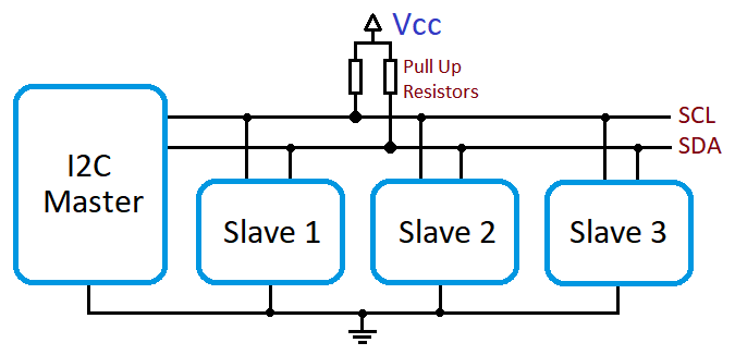
I2C Hardware
Devices on an I2C bus is always a master or a slave.
Master
Master is the device which always initiates a communication and drives the clock line (SCL). Usually a microcontroller or microprocessor acts a master which needs to read data from or write data to slave peripherals.
Slave
Slave devices are always responds to master and won’t initiate any communication by itself. Usually devices like EEPROM, LCDs, RTCs acts as a slave device. Each slave device will have a unique address such that master can request data from or write data to it.
I2C Protocol
I2C protocol is more complex than UART or SPI protocols as it using only 2 lines (one for clock and one for data) for to and fro communication. But usually we don’t need to worry about it as in most of the devices hardware itself will take care of these things.
As we explained above I2C buses have two kinds of devices, master and slave. In these always a master device takes ownership of the bus at a time and initiate data transfer.
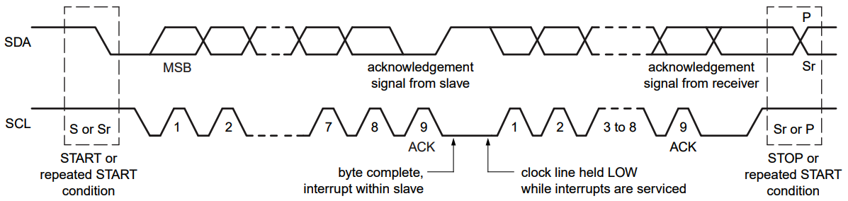
Start Condition
I2C start condition is issued by a master device to give a notice to all slave devices that the communication is about to start. Thus start condition triggers all slave devices to listen to the data in the bus. To issue start condition, the master device pulls SDA low and leaves SCL high. In the case of multi-master I2C there is a possibility that 2 masters wish to take ownership of the bus at the same time. In these cases the device which pull down SDA first gains the control of the bus.
Address Frame
Address frame is always send just after the first start condition during every communication sequence. In this master devices specifies the address of the slave device to which the master wants to communicate. There are basically 2 types of addressing 7-bit addressing and 10-bit addressing. In the 7-bit addressing mode, master sends address first (MSB first) followed by read/write (R/W) indicating bit (0 => Write, 1 => Read).
You can read about 10-bit addressing mode below.
Data Frames
Data frame(s) are transmitted just after the address frame. It can be send from master to slave OR from slave to master depending on the above R/W bit through SDA line. The master will continue generating required clock signals. Devices can send one or more than one data frame as per the requirements.
Stop Condition
Master device will generate stop condition once all data frames has been sent/received. As per I2C standards, STOP condition is defined as a LOW to HIGH transition on SDA line after a LOW to HIGH transition on SCL, with SCL HIGH. So SDA should not change status when SCL is HIGH to avoid false stop condition.
Repeated Start Condition
During an I2C communication, sometimes a master wants to send a specific command to a slave device and read back response right away. In this situation there is a possibility that another master (in case of multi-master bus) takes the control of the bus. To avoid these conditions I2C protocol defines repeated start condition.
In normal cases I2C master will send start condition, address + R/W bit, send or receive any number of bytes and mark the end by a stop condition. During repeated start condition, master will send START CONDITION instead of stop condition and will keep the control over the bus. Master can send any number of start condition using this method. Irrespective of the number of start conditions, transfer must be end by exactly one stop condition
Clock Stretching
We have seen that master device determines the clock speed in I2C communication. This avoid the need of synchronizing master and slave exactly to a predefined baudrate. But there can be some situations when I2C slave device is not able to cooperate with clock signals given by master. Clock stretching is the mechanism used to slow down master device for slave device to complete it’s operation.
I2C slave device is allowed to hold down the clock signal when it needs master to slow down on the 9th clock of every data transfer before the ACK stage.
Acknowledge (ACK) and Not Acknowledge (NACK)
Each byte of data in I2C communication includes an additional bit known as ACK bit. This bit provides a provision for the receiver to send a signal to transmitter that the byte was successfully received and ready to accept another byte.
10-bit Addresses
We seen above that I2C bus uses 7-bit addressing, which means that devices are limited to 127 devices and address clashes can happen. 10-bit address scheme is introduced to solve this problem. 10-bit address devices can be mixed with 7-bit devices and it increases the address range about 10 times.
I2C Characteristics
Open Drain – Bidirectional Communication
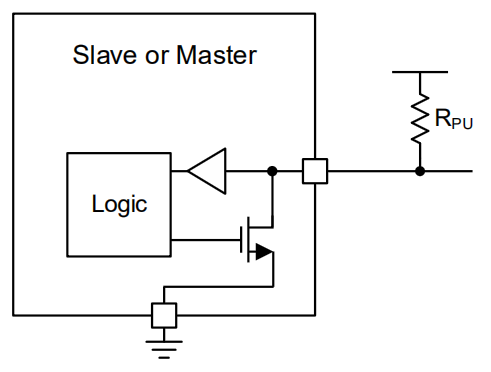
Open drain means all devices are using a MOSFET with open drain (not connected to anywhere else) to drive the bus voltage. This technique ensures easy bidirectional communication among multiple devices without any conflicts which may cause short circuit/excess currents if we connect in normal ways.
Thus the bus line may be pulled down to GROUND voltage if any of the MOSFET in a I2C device is ON or release the bus line and let it be pulled up by the pull up resistor.
Open Drain – Pulling Low
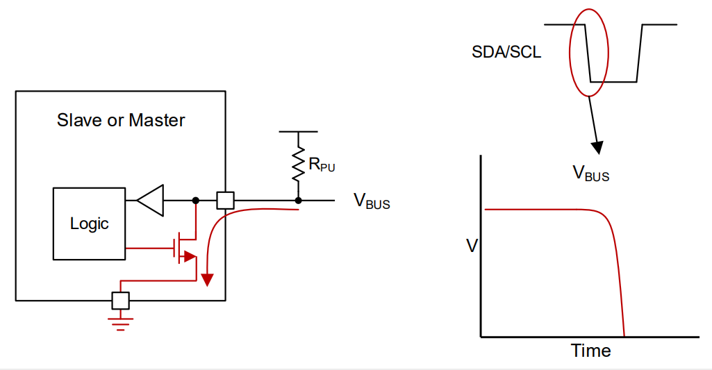
When the device needs to transmit LOW, it can switch ON the MOSFET, the bus will be pulled down (shorted to ground).
Open Drain – Releasing Bus
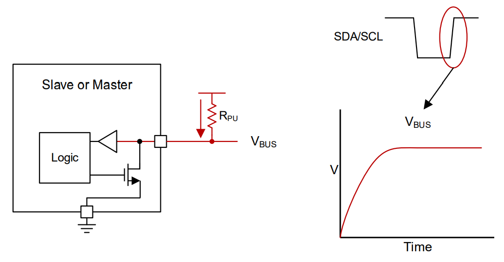
When a device needs to transmit HIGH, it can simply release the bus (MOSFET OFF). This leaves the bus floating and it will be pulled HIGH by the pull up resistors.
I2C Configurations
As explained above we can make I2C configurations basically in 2 ways.
Single Master I2C Bus
This is the simplest I2C bus configuration. Single master in the bus is responsible for all communications taking place in the bus. It will be providing necessary clock required for the communication with slave devices. The master device will specify the address of the particular slave device to which it needs to write data or from which it needs to read data. Only that particular slave device will respond for this.
Note : Communication is always initiated by a master device. Slave devices will use the bus only on request from the master device.
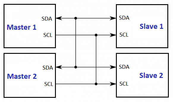
Multi-Master I2C Bus
In this case there will be more than one master device. Any master device is allowed to start communication or use the bus whenever it is required. If a master in a multi-master bus transmits a HIGH, bus see’s that the line is LOW (means another device is pulling down), it has to halt the communication because another device is using the bus.
Pros and Cons
Advantages
- Needs only 2 lines (SCL & SDA) + Ground as reference
- Supports up to 1008 slave devices
- Supports multi-master system
Disadvantages
- Needs more complex hardware
- Data rate less than SPI
Applications
- EEPROMs
- Real Time Clock ICs
- Temperature Sensors
- Accelerometers
- Gyrometers
- LCDs


Thank You for such a full and great explanation for both SPI and I2C. Thank You very much.