

5V Power Supply using 7805 Voltage Regulator with Design
In most of our electronic products or projects we need a power supply for converting mains AC voltage to a regulated DC voltage. For making a power supply designing of each and every component is essential. Here I’m going to discuss the designing of regulated 5V Power Supply.
Let’s start with very basic things the choosing of components
Component List :
- Step down transformer
- Voltage regulator
- Capacitors
- Diodes
Let’s get into detail of rating of the devices :
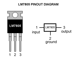
Voltage regulator :
As we require a 5V we need LM7805 Voltage Regulator IC.
7805 IC Rating :
- Input voltage range 7V- 35V
- Current rating Ic = 1A
- Output voltage range VMax=5.2V ,VMin=4.8V
Transformer :
Selecting a suitable transformer is of great importance. The current rating and the secondary voltage of the transformer is a crucial factor.
- The current rating of the transformer depends upon the current required for the load to be driven.
- The input voltage to the 7805 IC should be at least 2V greater than the required 2V output, therefore it requires an input voltage at least close to 7V.
- So I chose a 6-0-6 transformer with current rating 500mA (Since 6*√2 = 8.4V).
NOTE : Any transformer which supplies secondary peak voltage up to 35V can be used but as the voltage increases size of the transformer and power dissipation across regulator increases.
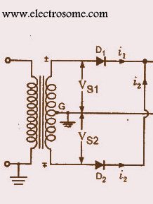
Rectifying circuit :
The best is using a full wave rectifier
- Its advantage is DC saturation is less as in both cycle diodes conduct.
- Higher Transformer Utilization Factor (TUF).
- 1N4007 diodes are used as its is capable of withstanding a higher reverse voltage of 1000v whereas 1N4001 is 50V
Capacitors :
Knowledge of Ripple factor is essential while designing the values of capacitors
It is given by
- Y=1/(4√3fRC) (as the capacitor filter is used)
1. f= frequency of AC ( 50 Hz)
2. R=resistance calculated
R= V/Ic
V= secondary voltage of transformer
- V=6√2=8. 4
- R=8.45/500mA=16.9Ω standard 18Ω chosen
3. C= filtering capacitance
We have to determine this capacitance for filtering
Y=Vac-rms/Vdc
Vac-rms = Vr/2√3
Vdc= VMax-(Vr/2)
Vr= VMax- VMin
- Vr = 5.2-4.8 =0. 4V
- Vac-rms = .3464V
- Vdc = 5V
- Y=0 .06928
Hence the capacitor value is found out by substituting the ripple factor in Y=1/(4√3fRC)
Thus, C= 2314 µF and standard 2200µF is chosen
Datasheet of 7805 prescribes to use a 0.01μF capacitor at the output side to avoid transient changes in the voltages due to changes in load and a 0.33μF at the input side of regulator to avoid ripples if the filtering is far away from regulator.
Circuit Diagram
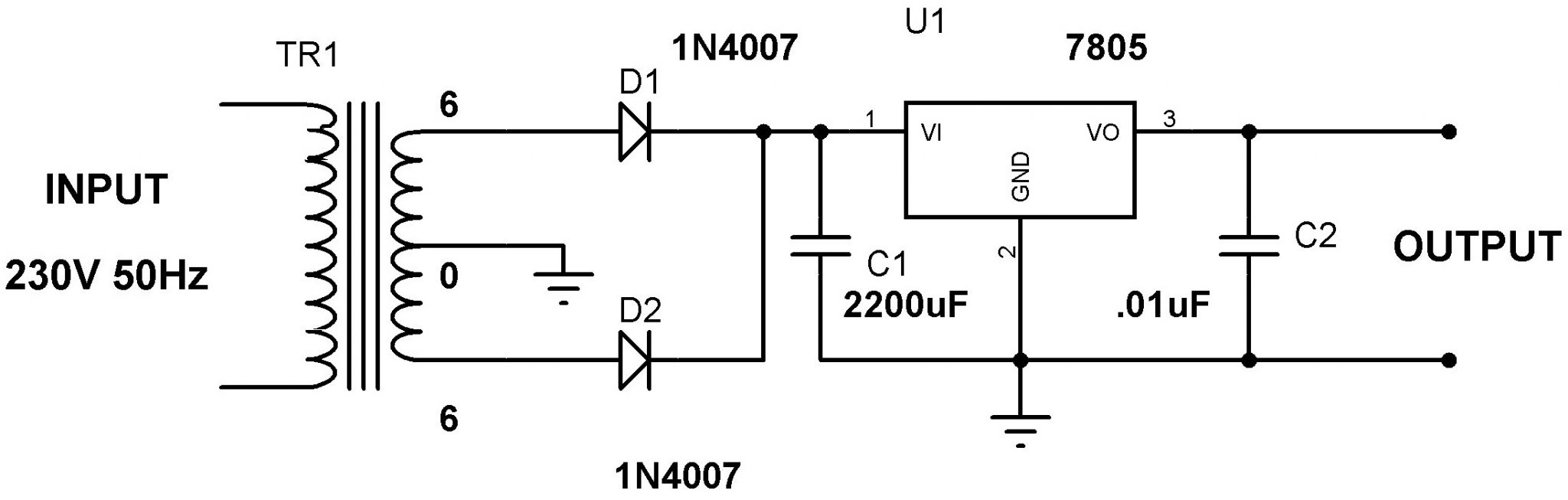


ripple factor
(Vr/2)×√3=0.3464
Vr/2√3=0.4/2√3=0.115
But you got 0.3464p, please explain or correct ASAP
can you specify what is y and how u got that formula ???
great article. simple for power supply design. transformer and other components actually makes it bulky.
power supply should be in Component form. like smps.
As per the data sheet of7805 the min input voltage should be 7.2 volts. Here in the circuit diagram it is shown 6 volts. Please clarify.
and if i want output max 5V 2A? what should i add to the circuit?
plz answer me!
and if i want output max 5V 2A? what should i addto the circuit plz?
It is the assumed load resistance.
18ohm, sorry
where have u used the 18k resistor?
Yes, 7805 maximum output capacity is 1A. So you should always use a current below it. And the current rating of the transformer also matters.
Whether the output will be 5V 1A DC?
7805 is a proven voltage regulator. You will get it for sure. Try in hardware.
hi there. im trying to design this in the Multisim program but i am unable to obtain the desired 5V output. instead, I am getting a constant 0.926pV output. I’ve tried changing the component values but I’m unable to obtain the expected result.
hello
thanks for giving specification of ICs 7805
Hi,
thanks for the post.
when calculating R it should not be from secondary transformer since during discharge current direction is into the load.
so R = Vc / load into current via 7805.
do you agree ?