

Bistable Multivibrator using 555 Timer
Contents
As the name indicates, a bistable multivibrator has 2 stable states. It can be switched from one state to another by providing an external trigger. It can be used for storing a binary digit (bit) as it has 2 stable states (0 or 1). So it is commonly used in digital circuits, where it is named as Flip Flop or Latches.
A bistable multivibrator can be easily constructed using the most popular and low cost 555 Timer IC.
Circuit Diagram – 555 Timer Bistable Multivibrator

In the above circuit 555 is wired as a bistable multivibrator. Two switches are provided to SET or RESET the output of 555 and an LED is used for indicating the output. Resistors R1 & R2 (10KΩ) are the PULL UP resistors for the switches. When the switches are open, 2nd, 4th pin will be in HIGH state and when the switches are closed it will go to LOW state. Resistor R3 is the current liming resistor connected in series with the LED. Capacitor C1 is commonly connected to 5th pin of 555 for avoiding high frequency noises.
Working
For the easy understanding of detailed working, I made a gif animation. You can see what happens internally when you press and release each switches.

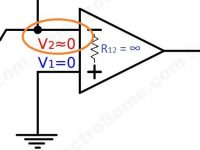
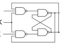
As shown in above internal diagram, there are three 5KΩ resistors in 555 connected in series to provide internal reference voltage for 2 comparators. A comparator is a device which will compare two voltages and indicate which one is larger. When the input voltage at +ive pin is greater than -ive pin, its output will be HIGH otherwise it will be LOW.
The -ive reference voltage of Upper Comparator is 2Vcc/3 and the +ive reference voltage is threshold input (6th pin). The +ive reference voltage of Lower Comparator is Vcc/3 and the -ive reference voltage is trigger input (2nd pin). So as per the 6V Vcc, the output of Upper Comparator will become HIGH when the threshold input (6th pin) voltage is higher than 4V. The output of Lower Comparator will become HIGH when the trigger input (2nd pin) voltage is lower than 2V. In the above circuit, output of Upper Comparator is always ZERO.
SR Flip Flop Truth Table
| S | R | RST | Q | Q’ |
|---|---|---|---|---|
| 0 | 0 | 1 | No Change | No Change |
| 0 | 1 | 1 | 0 | 1 |
| 1 | 0 | 1 | 1 | 0 |
| 1 | 1 | 1 | Undefined | Undefined |
| X | X | 0 | 0 | 1 |
Note : The output is taken from Q’ as an Inverting Buffer is used at the output stage.
So the working can be summarized as follows.
- In NORMAL STATE (No Switch is pressed) output of both comparators will be LOW. So RS flip flop maintains the previous state, so the output has NO CHANGE
- When the SET button is pressed TRIGGER input becomes LOW, output of LOWER COMPARATOR will become HIGH, SETs the output of flip flop, so the output becomes HIGH
- When the SET button is released it will got to NORMAL STATE (1). So the output has NO CHANGE, ie HIGH.
- When the RESET button is pressed, it will reset the flip flop. So the output goes LOW.
- When the RESET button is released it will again go to NORMAL STATE (1). So the output has NO CHANGE, ie LOW.
Design
There is nothing special to design here.
Pull up resistors R1 and R2 are chosen as 10K to maintain a low current when the switch is pressed. You can even use 33K also.

LED series resistor can be designed as follows.
R3 = (Vout – Vled)/Iled.
Where,
- Vout is the Output Voltage
- Vled is the LED Voltage
- Iled is the recommended maximum LED current
Note : You should choose a standard resistor whose resistance is greater than the calculated value.


