555 Timer IC
Contents
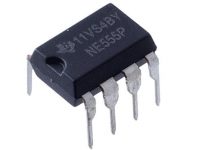
The 555 Timer is the one of the most versatile linear hybrid Integrated Circuit (IC) which is used in variety of pulse generation, timer and oscillator applications. In 1972, Signetics Corporation first introduced this device as the SE/NE 555.

Now a days it is manufactured by many companies in bipolar and in low power CMOS. It is widely used in electronics circuits as it is very simple and cheap method to produce accurate and highly stable time delays. It can be used for various timing applications from microseconds to hours range and can source or sink up to 200 mA current.
A dual version of 555 named as 556 is also available which has two independent 555 in one IC.
Internal Diagram of 555 Timer

From the above diagram we can find that the power supply to the timer can be given through pin 8 ( Vcc ) and pin 1 ( Gnd ). Vcc can be between +5v to 15v. Then we can find that a voltage divider is formed between Vcc and Gnd using three 5KΩ resistor. It is hypothesized that 555 got its name from these three 5KΩ resistors. Voltage at the junctions of these resistors will be 2/3 Vcc and 1/3 Vcc as all resistors are of same value which are used as the reference voltages of the comparators.
A comparator is a device which compares two voltage and indicate which one is larger. The trigger input of 555 (pin 2) is connected to the comparator with reference voltage 1/3 Vcc and the threshold input (pin 6) is connected to the comparator with reference voltage 2/3 Vcc. These reference voltages can be change using the Control Voltage Input (pin 5).
The output of comparators are directly given to the inputs of SR Flip Flop. Thus the output of the SR Flip Flop will be set according to the outputs of the comparator which in turn depends on the Trigger and Threshold inputs.
Pin Diagram

Pin Functions of 555 Timer
1. Ground
This is the ground pin or common pin of the IC. It should be connected to the negative terminal of the DC Power Supply.
2. Trigger
It is the pin connected to the inverting terminal of the lower comparator. As the name suggests it is used to trigger the timer. A negative trigger at this pin sets the flip flop. Precisely when the trigger voltage becomes less than Vt. Vt = 1/3 Vcc, When the Control Voltage (pin 5) is not used. Vt = 1/2 of the voltage at pin 5 when it is used.
3. Output
This is the output pin of the timer. It can source or sink 200 mA of current.
4. Reset
This pin is used to reset the timer. When the voltage at this pin becomes less than 0.7 V , the IC will reset and the output will be 0V. So in normal operations this pin will be tied to Vcc.
5. Control Voltage
This pin can be used to change the reference voltages of the comparators through this we can vary the timing.
6. Threshold
This pin resets the timer (makes output low) when the voltage given to it becomes greater than Vth provided the Trigger input remains HIGH. Vth = 2/3 Vcc when the Control Voltage is not using. Vth = Voltage given to Control Voltage when it is using.
7. Discharge
This pin is connected to the open collector of a transistor whose emitter is grounded and base is connected to compliment of output. So when the output is low, transistor becomes ON and collector becomes grounded. This pin is commonly used to Discharge the capacitor using for timing.
8. Vcc
This is the positive supply terminal of the IC. It can be connected to any voltage between 4.5 V through 15 V.
Operating Modes
Commonly 555 has 3 operating modes
.A multivibrator is an electronics circuit which is used to implement different types of two state ( HIGH or LOW ) devices such as oscillator (square wave generator), timer, flip flop etc.
- Monostable Mode : It is the multivibrator in which one state is stable, but the other state is unstable. A trigger causes the multivibrator to enter in the unstable state and it return to stable state after a particular time. This time is usually determined by the RC time constant. This multivibrator is also known as One Shot Multivibrator.
- Astable Mode : It is the multivibrator which has no stable states. It switches from one state to another after a time constant. The time constant is determined by the RC time constant.
- Bistable Mode : It is the multivibrator in which both states are stable. It can switch from one state to another by an external event or trigger.
Using the Output of a 555 Timer
The output of 555 can be HIGH ( 5v) or LOW (0v ) at any time. Its output is compatible with TTL and can be directly connected to TTL IC’s.

When the output of 555 is HIGH current is sourced from the IC and when the output is LOW 555 is sinking current. It can source or sink current up to 200mA. If the load requires more than 200mA we can connect an external driver transistor for that.


