

Wailing Siren using 555 Timer – Hobby Project
Contents
Today we shall talk about a really amazing circuit that produces a sound of a siren. There are different types of circuits that produce different kinds of sounds. Here is a simple circuit that produces wailing siren. The main principle of this circuit is to produce a wailing siren. The 555 timer IC is operated in astable mode. When the switch is pressed, speaker produces high pitch siren and when it is released, its pitch decreases and is switched off after 30 seconds.
Components Required
- 555 Timer IC
- BC547 Transistor
- BC557 Transistor
- 8Ω Speaker
- IC 7805
- 220KΩ Resistors
- 22KΩ Resistors
- 33KΩ Resistor
- 100KΩ Resistors
- 2x 10nF Capacitor
- 100μF Capacitor
- 9V Battery
- Battery Connector
- PCB
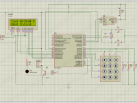
Circuit Diagram

Connections
The connections of the circuit are quite easy to make. The overall circuit can be divided into 4 parts.
- The first part consists of a switch, a 22K resistor and a 100uF capacitor.
- The second part consists of a BC547 transistor with a 100K resistorance connected to its base terminal and a 220K resistor connected between its base and collector terminals.
- The third part is the connection of the IC 555. The IC 555 is connected in astable mode so as to provide continuous output pulses at the output pin (Pin no 3).
- The pin no 1 is ground and it will be connected to negative terminal of the power supply.
- Pin no 2 and 6 are shorted and are connected to ground via 10nF capacitor. This is the capacitor that charges and discharges to give a continuous pulse at the output.
- Pin 3 is the output pin which is connected to the base of BC547 transistor Q2.
- The pin no 4 is the reset pin. It is an active low pin i.e it is activated when it has 0V on it. It is connected to Vcc when not in use in order to avoid false triggering.
- Pin no 5 is the control voltage. Datasheet specifies that it must be connected to ground via a 10nF capacitor(C3) at the time of no use condition.
- Pin no 7 is left open. We have no requirement of it in our circuit.
- The IC 555 is a 8 pin IC. It’s pin no 8 is Vcc which is connected to emitter of the transistor Q1.
- The fourth part of the circuit is the one consisting of BC547 transistor and speaker. The base terminal of BC547 transistor is connected to output pin i.e., Pin No. 3 of IC 555 and the emitter is grounded. The collector is connected to one end of the speaker. The other end of the speaker is connected to power supply.
Practical Implementation of Circuit

NOTE:
Here we have to use IC 7805 Regulator to get 5V as a Vcc for this circuit.
Description of Components
1) IC 555
The 555 timer IC is an integrated circuit (chip) used in a variety of timer, pulse generation, and oscillator applications. It is an 8 pin IC. It can be connected in three modes : Monostable Mode, Astable Mode and Bistable mode. In our circuit we have used it in astable mode to generate continuous square wave pulses.
An Astable Multivibrator is an oscillator circuit that continuously produces rectangular wave without the aid of external triggering. So Astable Multivibrator is also known as Free Running Multivibrator.
2) BC547 NPN Transistor
The BC547 transistors can be used in various applications as amplifier, switches etc. In our circuit there are 2 transistors.
One is used to drive the 8 ohm speaker and other is used as a switch for the overall circuit of IC 555 connections.
3) 8 ohm speaker
This is the component that produces the sound in our circuit. We must keep in mind that this speaker does not produce any sound with the constant DC current supply. Speaker used here is a 8 ohms speaker. Internally, speaker will have voice coil, diaphragm and magnet. When the electrical signals are applied to the voice coil electromagnetic waves are generated around the coil and it interacts with the magnetic field of the permanent magnet. Thus the permanent magnet and the induced magnetic field repel and attract each other and thus producing the electric signal changing its polarity. Thus the coil moves back and forth as a result of this electric signal. Thus this creates vibrations as the diaphragm moves continuously. These vibrations are responsible for producing sound.
Working of the Circuit
If we press a switch, the siren starts wailing and gradually increases its sound.
If we released a switch, the siren sound decreases gradually. It does not stop instantaneously.
The 10nF capacitor C3 is connected to pin no. 6 which charges and discharges to provide oscillation at the output.
The Vcc pin of the IC 555 receives supply when the BC547 transistor Q1 gets conducted by pressing a switch. The BC547 transistor gets conducted after reaching a bias voltage.
555 timer gets a supply after the activation of switch. Once the timer gets a supply, the 10nF Capacitor C2 starts charging and charges till to the peak value 2/3Vcc. The capacitor C2 starts discharging after reaching the peak value 2/3 Vcc and discharges until it reaches to 1/3 Vcc.
After this it will again start charging and this cycle continues resulting in a continuous square wave output at the pin no 3 of IC.
Applications
- This circuit can be used as an alarm in disaster management system.
- It can be used as a signal for completion for some task.
- It can be used in offices for indication lunch breaks.
- It can be used at the airports to drive away the birds from the runway.


u have mentioned that the 555 is working in astable mode as per your circuit. Then without any connection to pin7 of 555, how come the capacitor C3 discharges ? Please explain,I am confused.