

Read Modify Write Problem with Mid-Range PIC Microcontrollers
Contents
RMW Problem with PIC 16F Family
Microchip’s mid-range PIC Microcontrollers use a sequence of operations : Read, Modify and Write to change output state of a pin. In certain circumstances RMW operations might cause unexpected behavior of outputs. You might have already experienced this issue and struggled with it as you can’t find exact reason with microcontrollers unexpected behavior. Mid-Range PIC Microcontroller uses two registers, TRIS and PORT to control the direction and status of an IO pin respectively.
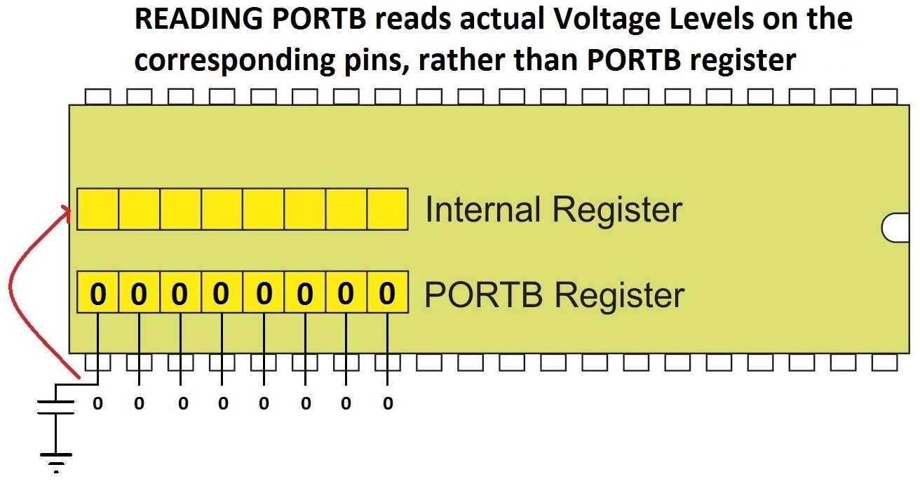
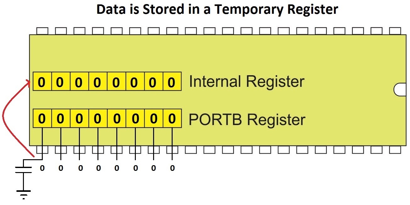
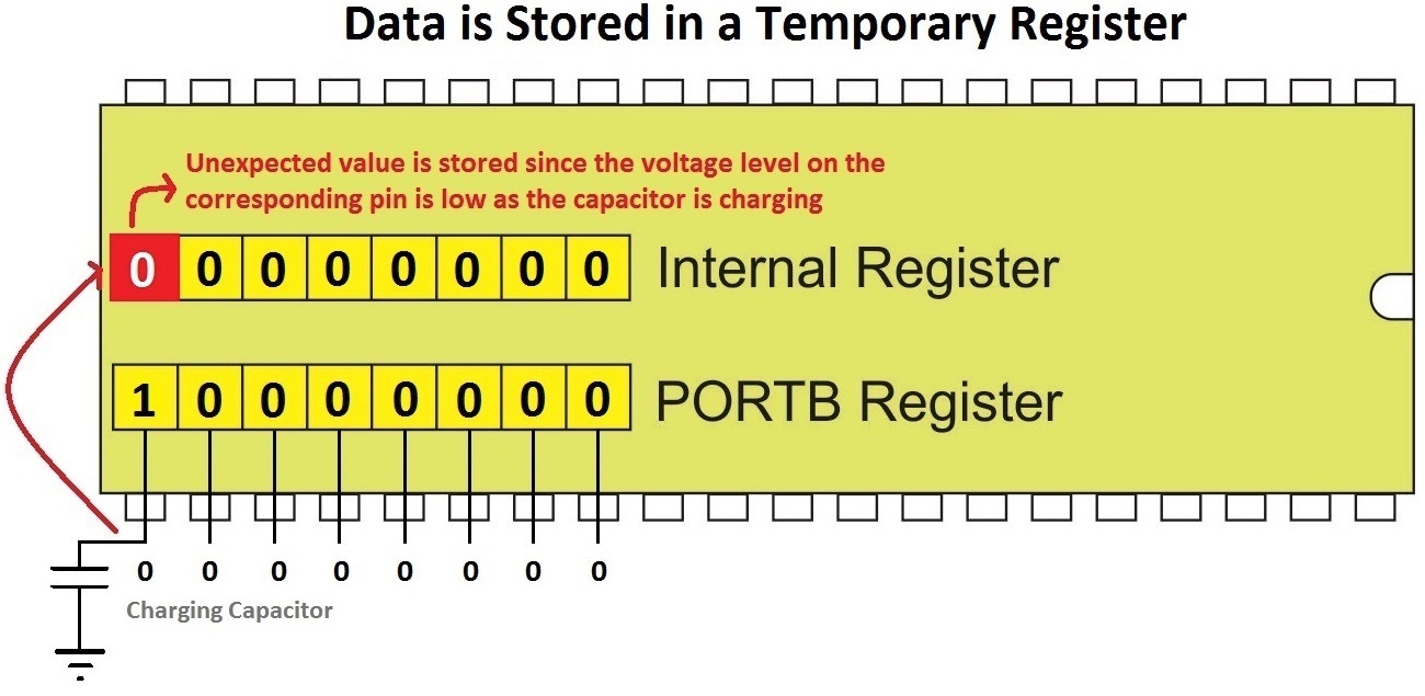
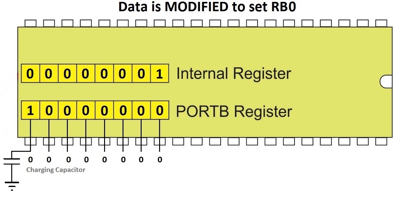
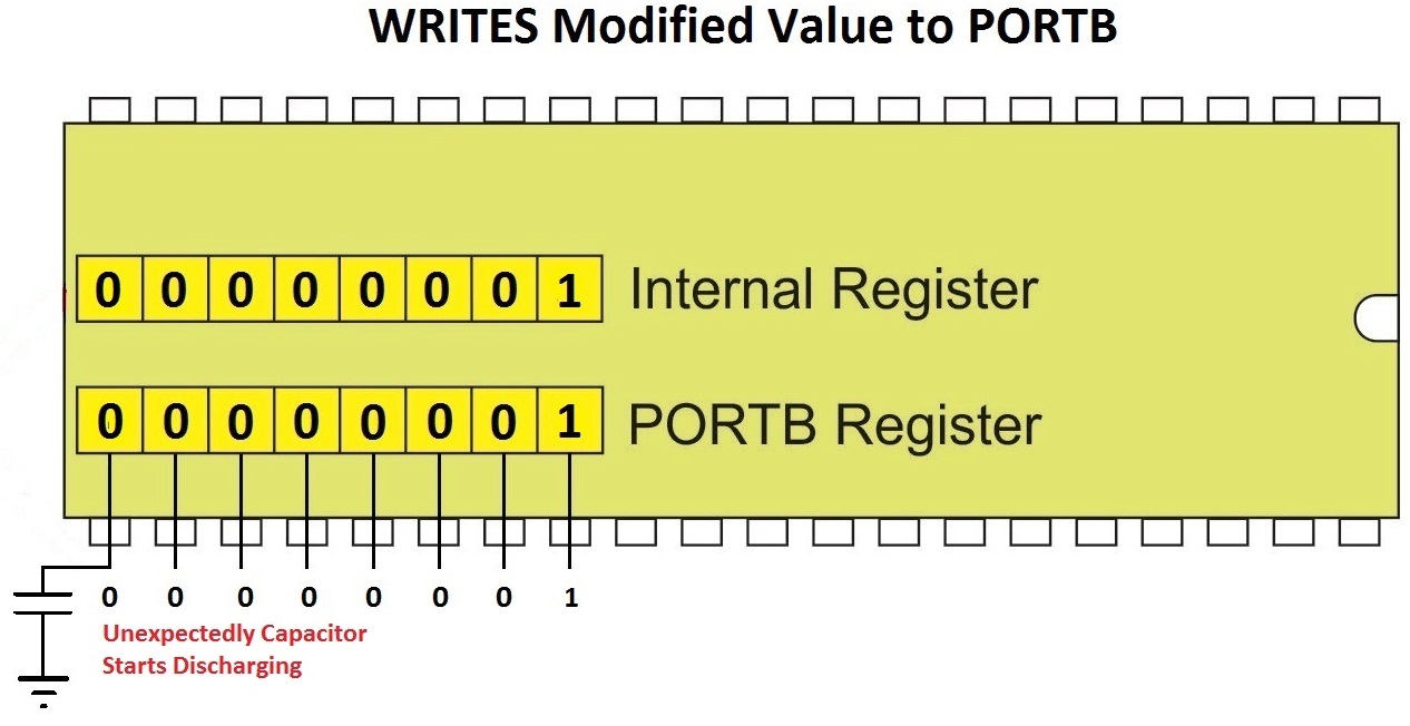
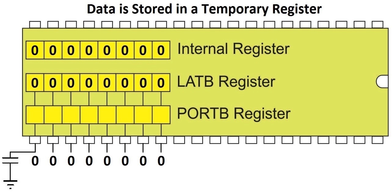
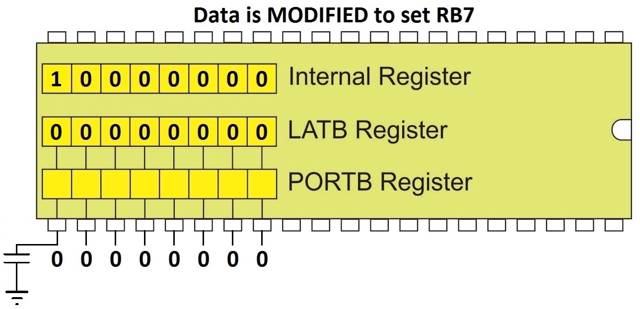
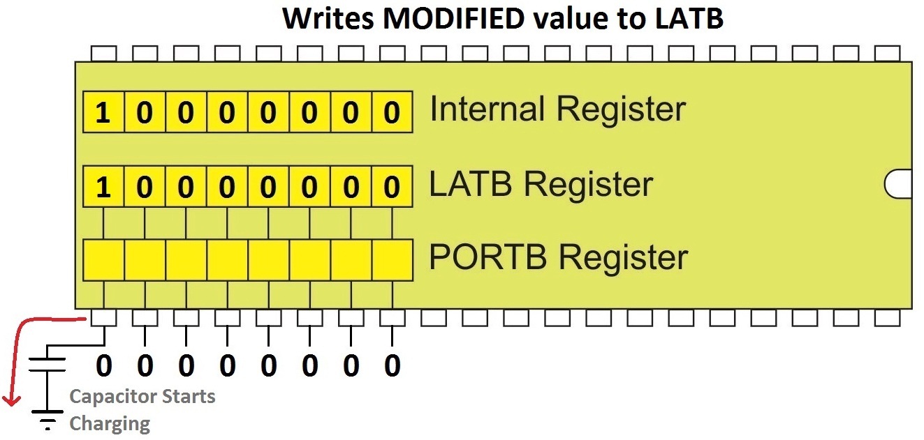
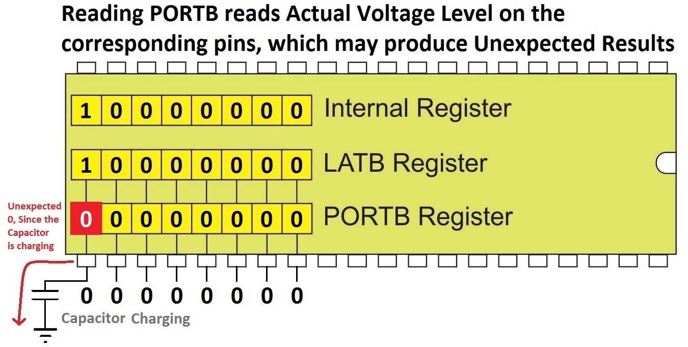
When you try to change the status of a specific pin, consider 7th bit of PORTB (RB7), the microcontroller reads all 8 bits of PORTB register and stores this data in a temporary register. Then modifies the 7th bit as per the instruction and the modified data is written back to PORTB. This process of modifying the output of a pin can cause unexpected behavior as the PORT Read operation reads the actual state of physical pin.
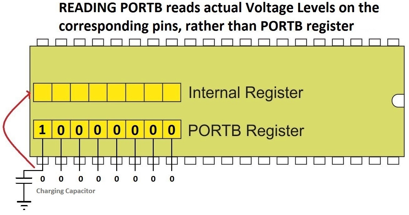
The actual physical state (voltage level) of a pin may be different from the value written to PORT register in certain instances. For example,
- When the output pin is connected to high inductance or capacitance loads.
- When the output pin is connected to LEDs without current limiting resistors.
- When the output pin drives a transistor without base resistor.
- When the output pin is shorted to ground.
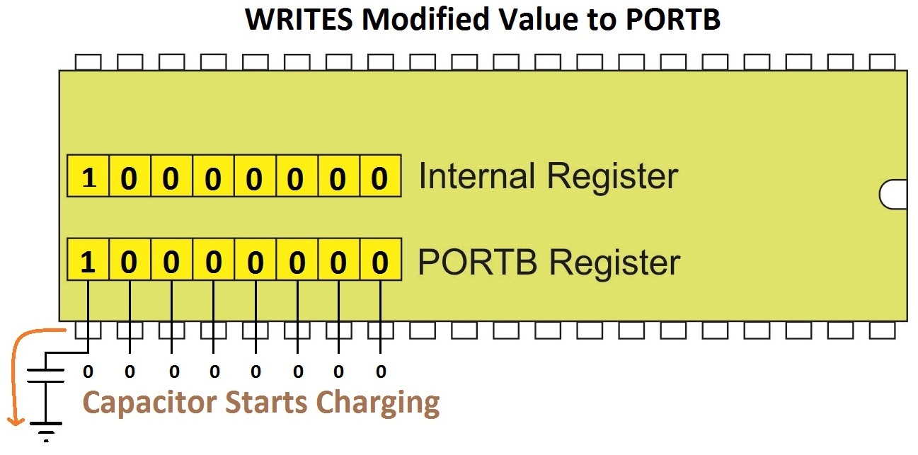
If a high value capacitor is connected to a pin, it will take some time to charge the capacitor when the pin is set to HIGH.
The following example will help you to understand Read Modify Write problem.
Let’s assume that PORTB is initialized to 0 and we are going to execute the following commands.
RB7 = 1;
RB0 = 1;
A discharged capacitor is connected to pin RB7. The first command RB7=1; will trigger RMW operation on PORTB as illustrated below.
 |
 |
 |
 |
The second command RB0=1; will also trigger another RMW operation on PORTB as illustrated below. (Click on the image to see enlarged image)
 |
 |
 |
 |
How to Solve this problem ?
- Insert a delay after RB7 = 1 such that sufficient time is provided for the charging of capacitor.
- Modify the entire PORTB register in a single step, PORTB = 0b10000001;
- Use Enhanced Mid-Range PIC Microcontrollers (PIC16F1XXX).
- Use PIC 18F Microcontrollers.
LAT Register Solves the Problem
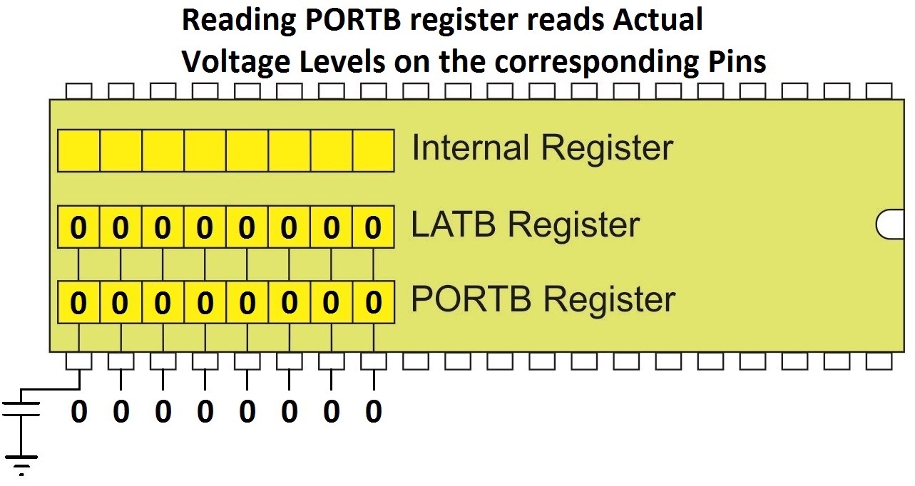
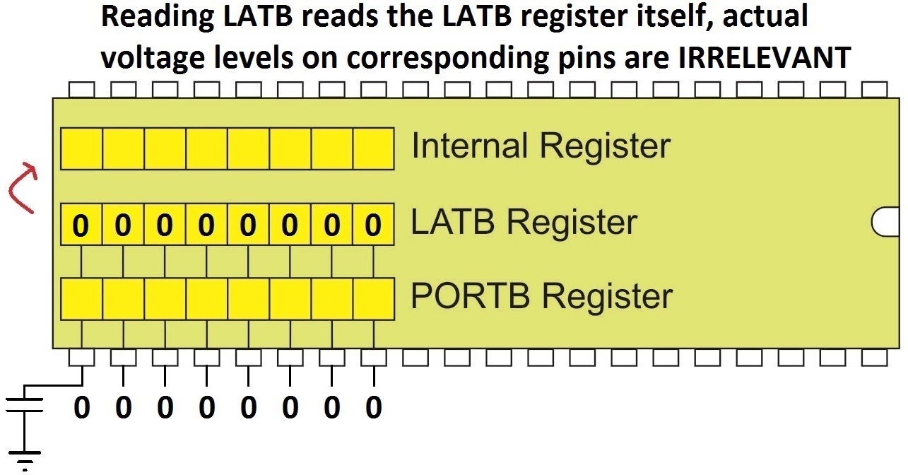
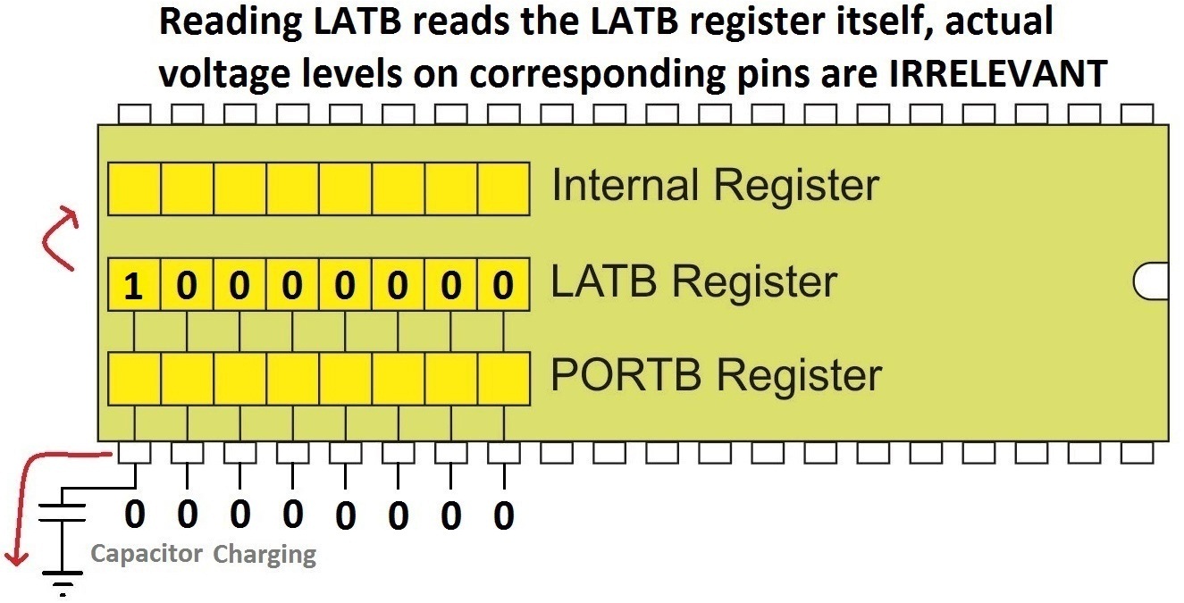
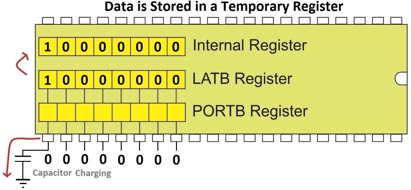
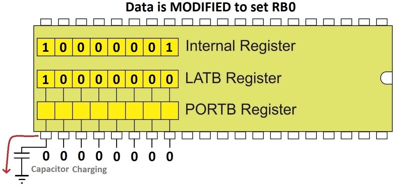
In PIC 18F and PIC 16F1XXX familys Read Modify Write (RMW) Problem is solved by adding LAT register. LAT stands for Port Latch. Thus each port is associated with three registers TRIS, PORT and LAT. As before TRIS register determines the direction of each digital IO pin, ie Input or Output. PORT register should be used to read data from Input pins, ie it reads Actual Voltage Levels of the pins as in 16F. LAT register is used to write data to Output pins. Writing data to LAT register is equivalent to a PORT register, but reading LAT register reads the Port Latch (LAT register) regardless of the physical state (voltage level) of the corresponding pin. Thus RMW problem will not occur in PIC 18F microcontrollers if we are using LAT register to write data as below.
LATB7 = 1;
LATB0 = 1;
Let’s assume that LAT register is initialized to 0 initially. The following images will help you to understand the action of LAT register. (Click on the image to see enlarged version)
 |
 |
 |
 |
 |
 |
 |
 |
 |
 |
You may use PORT register to write outputs similar to 16F family but it is not recommended due to Read Modify Write Problems.


registered on this website just to comment: thanks! very well explained:)
very good …. thx alot