

Getting Started with MPLAB XC8 Compiler – LED Blinking
Contents
In this tutorial we will learn How to Blink an LED with PIC Microcontroller using MPAB XC8 Compiler. Recently Microchip released a series of development tools including MPLAB X IDE and MPAB XC Compilers. MPLAB X IDE is a software that runs on a computer intended to develop applications for Microchip’s Microcontrollers and Digital Signal Controllers. It can be used with Windows, Mac and Linux Operating Systems. It is called an Integrated Development Environment as it provides comprehensive facilities to the developers. Unlike previous versions of MPLAB, MPLAB X IDE is based on open source NetBeans IDE by Oracle.
MPLAB XC Compilers are general solutions for all Microchip PIC Microcontrollers and it can be used for any Project. It replaces all MPLAB C and Hi-Tech C compilers. Microchip recommends every developers to use MPLAB XC Compilers. These compilers integrates with MPLAB X IDE to provide full graphics front end.
In this example project we will blink an LED using PIC 16F877A Microcontroller. For that we will use MPLAB X IDE and MPLAB XC8 Compiler. You can download MPLAB X IDE and XC8 Compiler from the respective pages.
You should install Java before installing MPLAB X.
- Download and Install MPLAB X IDE.
- Download and Install MPLAB XC8 Compiler.
- Open MPLAB X IDE.
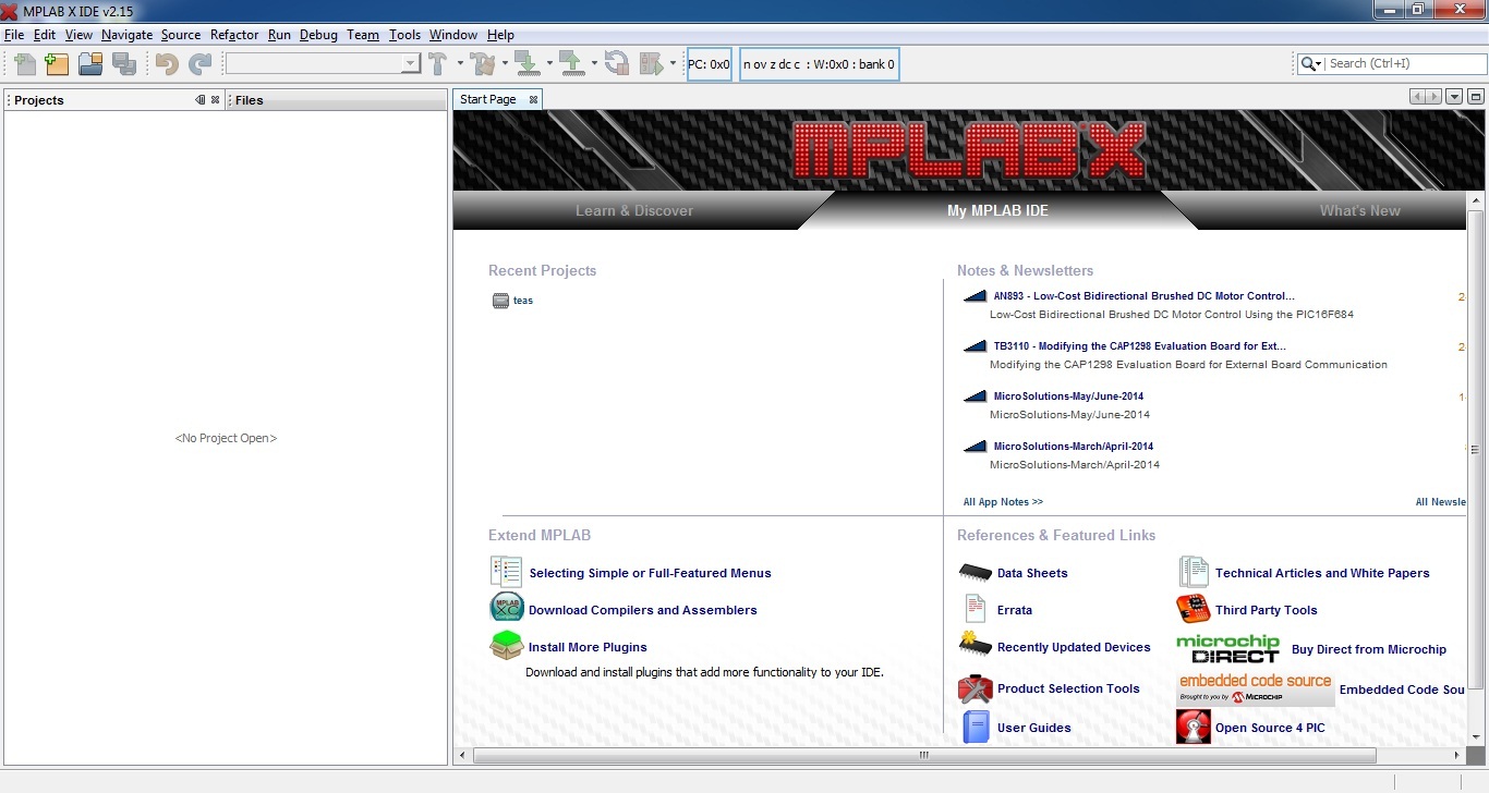
- Click on File >> New Project
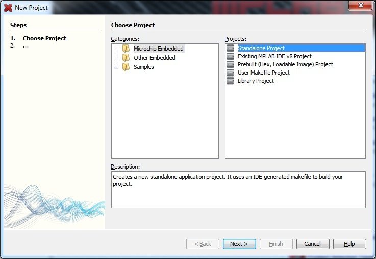
- Select Microchip Embedded >> Standalone Project
- Click Next
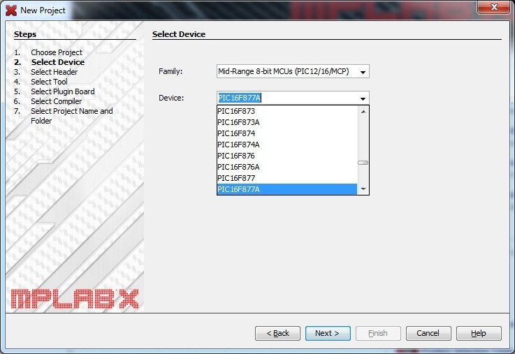
- Select Family and Device.
- Click Next
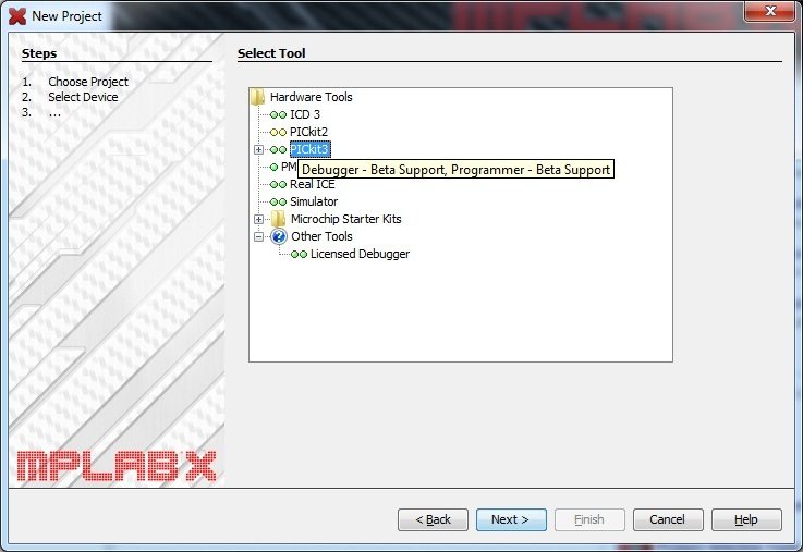
- Select your Hardware Tool. Don’t worry if your programmer is not supported. You can directly burn the hex file after building the project.
- Click Next
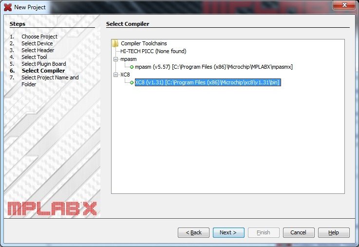
- Select the Compiler XC8.
- Click Next
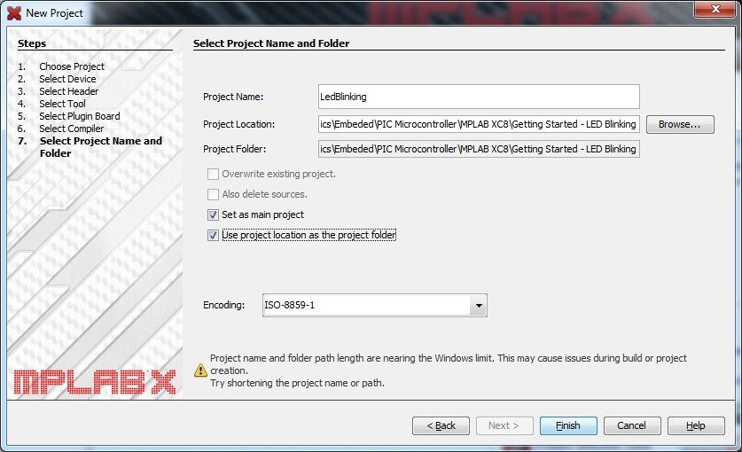
- Give Project Name, Project Location etc.
- Click Finish
- Right Click on the Source Files in the Project Tree.
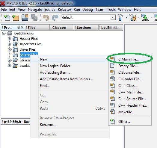
- Select New >> C Main File
- Provide Name and Location of the file
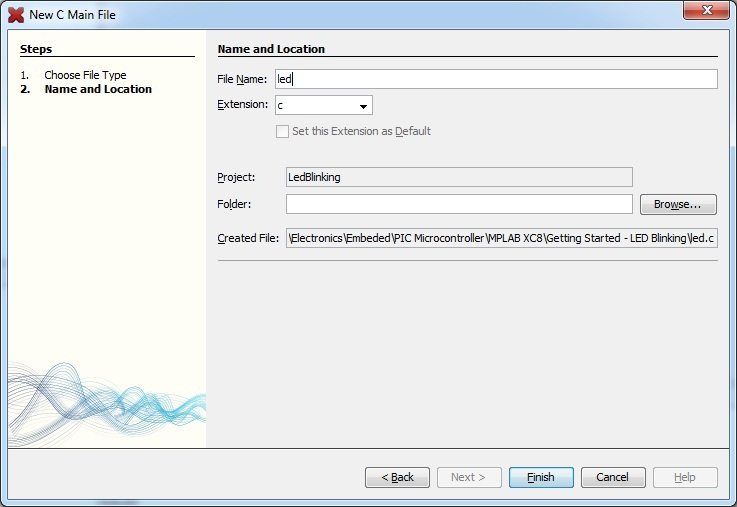
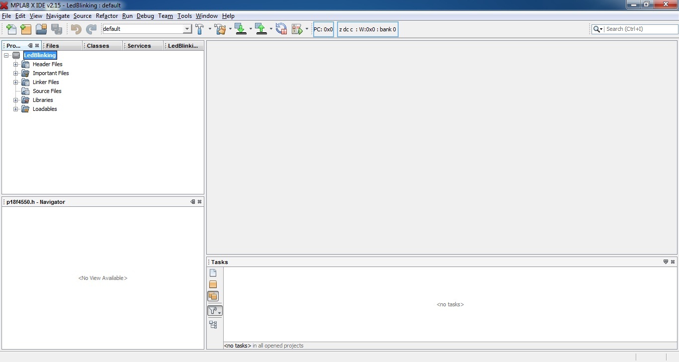
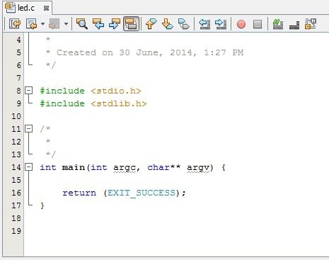
- New Source file is created, you can add code here.
MPLAB XC8 Programming
- Input Outputs pins of a PIC Microcontroller is divided into different PORTS containing a group of GPIO (General Purpose Input Output) pins.
- Since PIC 16F877A is an 8-bit microcontroller, each PORT contains 8 Input Output pins.
- In 16F Microcontrollers, each port is associated with two registers : TRIS and PORT. Eg : TRISB, PORTB, TRISD, PORTD.
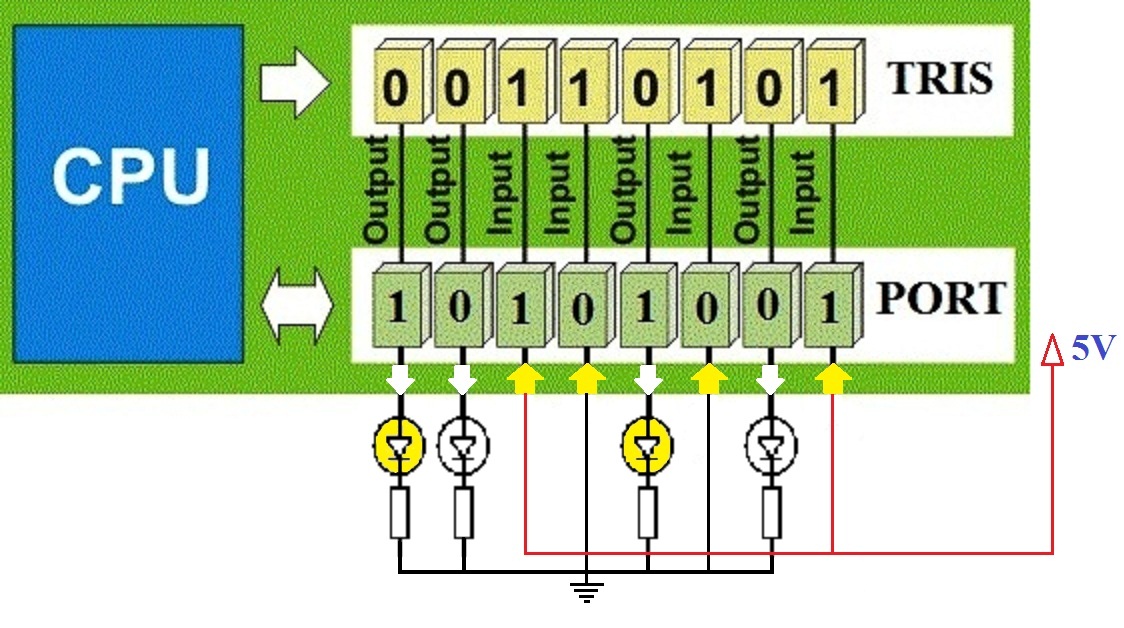
- TRIS stands for Tri-State, it determines the direction of each GPIO pins. Logic 1 at a particular bit of TRIS register makes the corresponding pin Input while Logic 0 at a particular bit makes the corresponding pin Output.
- All Input pins will be in Hi-Impedance state.
- PORT Register is used to Read Data from or Write Data to Input Output pins.
- For an Output pin (TRIS bit is 0), Logic 1 at PORT register makes the corresponding pin Logic High (VDD) and Logic 0 at PORT register makes the corresponding pin Logic Low (VSS).
- Since PIC 16F877A is a 5V device, VDD = 5V and VSS = 0V.
- PORT Read operation reads the Physical State (actual Voltage Level) of IO pins. If an IO pin is at a potential near to VDD, corresponding PORT bit will be Logic 1 and if it at a potential near to VSS, corresponding PORT bit will be Logic 0.
Writing Registers
You can write to PORT and TRIS Registers entirely or bit by bit.
Writing Bit by Bit :
TRISC0 = 1; //Makes 0th bit of PORTC Input
TRISC5 = 0; //Makes 5th bit of PORTC Output
RB3 = 1; //Makes 3ed bit of PORTB at Logic High
RB7 = 0; //Makes 7th bit of PORTB at Logic Low
Writing Entire Register
You should be familiar with following C Programming concepts.
- A number with a prefix ‘0b’ indicates a binary number.
- A number with a prefix ‘0’ indicates an octal number.
- A number with a prefix ‘0x’ indicates a hexadecimal number.
- A number without prefix is a decimal number.
Let’s see some examples…
| Decimal | Binary | Octal | Hexadecimal |
|---|---|---|---|
| 0 | 0b00000000 | 00 | 0x00 |
| 1 | 0b00000001 | 01 | 0x01 |
| 128 | 0b10000000 | 0200 | 0x80 |
| 255 | 0b11111111 | 0377 | 0xFF |
PORTB = 0xFF; //Makes all pins of PORTB Logic High
TRISC = 0x00; //Makes all pins of TRISC Output
PORTD = 128; //Makes 7th bit of PORTD Logic High
Code – LED Blinking
#define _XTAL_FREQ 8000000

#include <xc.h>

// BEGIN CONFIG
#pragma config FOSC = HS // Oscillator Selection bits (HS oscillator)
#pragma config WDTE = ON // Watchdog Timer Enable bit (WDT enabled)
#pragma config PWRTE = OFF // Power-up Timer Enable bit (PWRT disabled)
#pragma config BOREN = ON // Brown-out Reset Enable bit (BOR enabled)
#pragma config LVP = OFF // Low-Voltage (Single-Supply) In-Circuit Serial Programming Enable bit (RB3 is digital I/O, HV on MCLR must be used for programming)
#pragma config CPD = OFF // Data EEPROM Memory Code Protection bit (Data EEPROM code protection off)
#pragma config WRT = OFF // Flash Program Memory Write Enable bits (Write protection off; all program memory may be written to by EECON control)
#pragma config CP = OFF // Flash Program Memory Code Protection bit (Code protection off)
//END CONFIG

int main()
{
  TRISB0 = 0; //RB0 as Output PIN
  while(1)
  {
    RB0 = 1;  // LED ON
    __delay_ms(1000); // 1 Second Delay
    RB0 = 0;  // LED OFF
    __delay_ms(1000); // 1 Second Delay
  }
  return 0;
}
First statement #define _XTAL_FREQ 8000000 defines the clock frequency of the microcontroller which is used to calculate delays in __delay_ms() function. Second statement #include <xc.h> includes the header file xc.h which contains the definition of __delay_ms() function and TRIS, PORT registers.
Next is #pragma config directives, which is used to tell the compiler to set Configuration Bits of PIC Microcontroller. You can generate it using the MPLAB IDE as following.
- Go to Window >> PIC Memory Views >> Configuration Bits
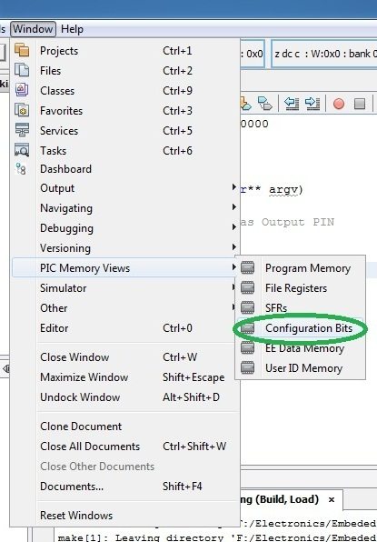
- You can select the configuration at the bottom of the IDE as shown below
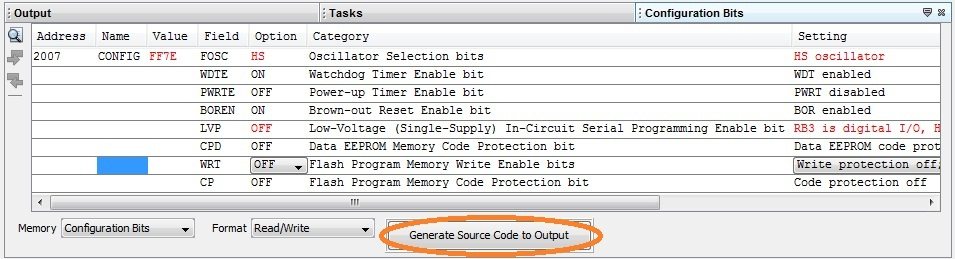
- Click Generate Source Code to Output

- You can simple copy paste this generated code to code editor.
- Then enter the remaining code for the blinking of LED.
- Build the Project
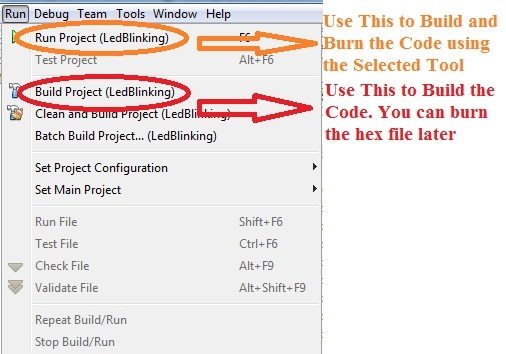
- Hex File will be generated in the location Your Project Folder >> dist >> default >> production
Circuit Diagram
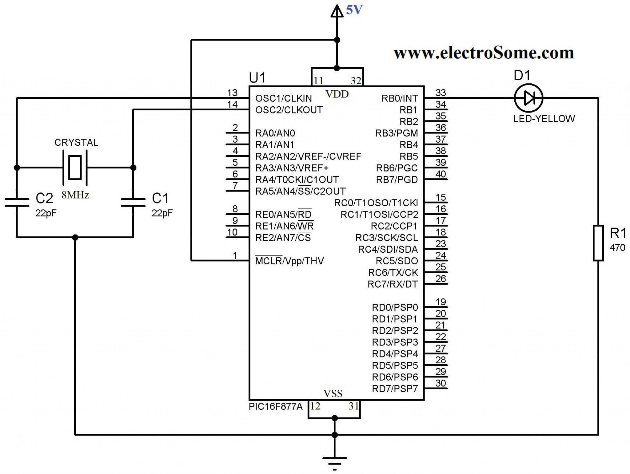
VDD and VSS of the PIC Microcontroller is connected to +5V and GND respectively. 8MHz crystal oscillator is used to provide necessary clock for the operation of the microcontroller. 22pF capacitors are used to stabilize the clock generated by crystal oscillator. An LED is connected to RBO (Pin 33) via a 470Ω resistor to limit the current.
Download Here
You can download entire project files here…


Hi Paul,
You may refer this article, https://electrosome.com/lcd-pic-mplab-xc8/
Good.
Please does mplabx, xc8 compiler have lcd in-built library function?
How can I write or read from lcd in mplabx?
PIC 16F877A does’t have any internal oscillators. And crystals are still used a lot where accurate and stable clocks are required.
Crystal? High speed internal RC oscillator has been mainstream since the stone age 🙂 But good article still.
Are you sure that you created the project properly ? You have to select XC8 compiler while creating the project.
Good afternoon sir,please i need help regarding the mplab x ide v4.05 and xc8 compiler v2.10 i just install.it is showing “cannot find inlude also #include highlighted in red.please how do i reolve this i have been searching for way out in the internet
Please Can you help with a school project?
Note I am using a program Micro-C
You can declare the variable as a constant…… like const int a = 10;
I’m looking for how store variable on flash instead ram. In AVR-gcc is simply, but in XC 32 or 8 i can’t found this one
Sir;
I need a pic16F877A in mplab x ide program of when switch is pressed led on and again switch is pressed led off.
Sir;
I need a pic16f877a in mplab x ide program of when switch is pressed led on and again switch is pressed led off.
what is the use #pragma,,, i’m using mikro c , in that i’m not having anything like this #pragma y, and in mikro c how the configuration bits are set?
Hi Ligo George, thank you for this content,,,,i brought your product(programmer) from eBay and followed all these steps exactly,but i am getting this error(red under line) “cannot find include file “.When i build this program,the program build successfully,but led is not blinking.(MPLAB X IDE V3.60,electrosome programmer,pic16f877a,pickit2 are used here). Please help.
https://uploads.disquscdn.com/images/aab2bd3d2cd3ee39f161531773f75b1c6d9350671dad2dea64417475b42cc50d.jpg
what is the changes when I use dsPIC30F2020 instead?
I downloaded the project files you had given here. But I cannot open it in my MPLAB X. I actually needed help in writing the header file. xc.h. I’m using PIC16F15356 for my project
you could also use this , for (int i = 0;i <20;i ++) _delay_ms(50);
As 20 x 50 = 1000 ms which is one second
I have downloaded and installed both IDE and the Compiler (MPLAB X IDE and MPLAB XC8 Compiler). but when I try to create a new project, it doesn’t let me choose the XC8 Compiler. However, I have an other Compiler(mpasm) but I don’t know how to access it (it’s header file). most of the time I’m using pic.h to program PIC16F877. but now it’s not working for me. Please help.
Kindly use our forums ( https://electrosome.com/fourms/ ) and put your complete code there.
I haven’t yet used 16F690. But watchdog timer will work fine without any problems.
Kindly use our forums ( https://electrosome.com/forums/ ) for asking doubts outside the scope of above article.
I’m trying some basic stuff on the PIC18f4455 and for some reason I can’t change the voltage level on the pins. Code compiles, downloads into the chip, but that’s it. No blinky, no nothing… Any ideas? ADC is turned off, btw.
Hi Ligo, great website I really enjoy your work. Just wondering have you ever managed to get the WDT of a PIC16F690 to work using XC8 compiler. Regards, Ferg.
If the error is inline delay argument too large, you need to make a user defined function and call it.
like this :
void Delay10(unsigned a)
{
for(;a>0;a–)
{
__delay_ms(10);
}
}
Image not clear. Please post the error.
What error ?
you forgot “include “
like this…..
sir i delay time error shows while code has been typed….pls help me
This is the image
First than all, thank you for the information. But I have a problem and I wonder if you could help me. When I try to select the compiler it doesn’t say nothing about the XC8 and I want to know why. Did I make a mistake in the installation? or maybe is the new version? How should I proceed?
Thanks for your attention.
Thank you for the information I will give that a try.
You can simply use if() control statements.
Thanks for this tutorial, this works really well. How can i use this block of code 3 times in a program? I want different delay times that I can input from a switch. I cannot figure out how to activate only one at a time.
Check the configuration bits in the program. Turn OFF LVP etc.
hello LIGO,
May i have your Email-ID
1.) I Am using Pic18F4520 Controller.
i have made my mclr pin positve i.e +5V applied to it.
also used crystal of 10Mhz hence capacitor of 15 pF. and in config had selected oscilator mode as HS.
I have wrote a program to blink led but it’s not working practically but in simulation it’s perfectly fine.
2.)One more i found that i have to insert a small wire at pin NO. RB5 the on the PIC DEM 2 Plus (old) it’s working fine
Plz help me..
i am attaching my code.
My main Program:
#include
#include
#include
#include “_config.h”
#include
void delay(unsigned char x)
{
for(unsigned char i=0;i<=x;i++)
for(unsigned char j=0;j<=135;j++);
}
void main()
{
while(1)
{
TRISB= 0;
LATB = 0xFF;
delay(100);
//LATB = 0xF0;
//delay(250);
LATB = 0x00;
//delay(100);
//LATB = 0x0F;
delay(100);
}
}
Config File:
#include
// #pragma config statements should precede project file includes.
// Use project enums instead of #define for ON and OFF.
// CONFIG1H
#pragma config OSC = HS // Oscillator Selection bits (HS oscillator)
#pragma config FCMEN = OFF // Fail-Safe Clock Monitor Enable bit (Fail-Safe Clock Monitor disabled)
#pragma config IESO = OFF // Internal/External Oscillator Switchover bit (Oscillator Switchover mode disabled)
// CONFIG2L
#pragma config PWRT = OFF // Power-up Timer Enable bit (PWRT disabled)
#pragma config BOREN = OFF // Brown-out Reset Enable bits (Brown-out Reset disabled in hardware and software)
#pragma config BORV = 3 // Brown Out Reset Voltage bits (Minimum setting)
// CONFIG2H
#pragma config WDT = OFF // Watchdog Timer Enable bit (WDT disabled (control is placed on the SWDTEN bit))
#pragma config WDTPS = 32768 // Watchdog Timer Postscale Select bits (1:32768)
// CONFIG3H
#pragma config CCP2MX = PORTC // CCP2 MUX bit (CCP2 input/output is multiplexed with RC1)
#pragma config PBADEN = ON // PORTB A/D Enable bit (PORTB pins are configured as analog input channels on Reset)
#pragma config LPT1OSC = OFF // Low-Power Timer1 Oscillator Enable bit (Timer1 configured for higher power operation)
#pragma config MCLRE = ON // MCLR Pin Enable bit (MCLR pin enabled; RE3 input pin disabled)
// CONFIG4L
#pragma config STVREN = ON // Stack Full/Underflow Reset Enable bit (Stack full/underflow will cause Reset)
#pragma config LVP = ON // Single-Supply ICSP Enable bit (Single-Supply ICSP enabled)
#pragma config XINST = OFF // Extended Instruction Set Enable bit (Instruction set extension and Indexed Addressing mode disabled (Legacy mode))
// CONFIG5L
#pragma config CP0 = OFF // Code Protection bit (Block 0 (000800-001FFFh) not code-protected)
#pragma config CP1 = OFF // Code Protection bit (Block 1 (002000-003FFFh) not code-protected)
#pragma config CP2 = OFF // Code Protection bit (Block 2 (004000-005FFFh) not code-protected)
#pragma config CP3 = OFF // Code Protection bit (Block 3 (006000-007FFFh) not code-protected)
// CONFIG5H
#pragma config CPB = OFF // Boot Block Code Protection bit (Boot block (000000-0007FFh) not code-protected)
#pragma config CPD = OFF // Data EEPROM Code Protection bit (Data EEPROM not code-protected)
// CONFIG6L
#pragma config WRT0 = OFF // Write Protection bit (Block 0 (000800-001FFFh) not write-protected)
#pragma config WRT1 = OFF // Write Protection bit (Block 1 (002000-003FFFh) not write-protected)
#pragma config WRT2 = OFF // Write Protection bit (Block 2 (004000-005FFFh) not write-protected)
#pragma config WRT3 = OFF // Write Protection bit (Block 3 (006000-007FFFh) not write-protected)
// CONFIG6H
#pragma config WRTC = OFF // Configuration Register Write Protection bit (Configuration registers (300000-3000FFh) not write-protected)
#pragma config WRTB = OFF // Boot Block Write Protection bit (Boot block (000000-0007FFh) not write-protected)
#pragma config WRTD = OFF // Data EEPROM Write Protection bit (Data EEPROM not write-protected)
// CONFIG7L
#pragma config EBTR0 = OFF // Table Read Protection bit (Block 0 (000800-001FFFh) not protected from table reads executed in other blocks)
#pragma config EBTR1 = OFF // Table Read Protection bit (Block 1 (002000-003FFFh) not protected from table reads executed in other blocks)
#pragma config EBTR2 = OFF // Table Read Protection bit (Block 2 (004000-005FFFh) not protected from table reads executed in other blocks)
#pragma config EBTR3 = OFF // Table Read Protection bit (Block 3 (006000-007FFFh) not protected from table reads executed in other blocks)
// CONFIG7H
#pragma config EBTRB = OFF // Boot Block Table Read Protection bit (Boot block (000000-0007FFh) not protected from table reads executed in other blocks)
[email protected]
Hi-Tech C is the old compiler. Microchip stopped the support for Hi-Tech C.
The latest one is X8.
Hi Ligo. Can you tell me please, is it a big difference between HiTech C and XC8? I mean a have a HiTech source code and I would like to transfer to XC8 as my device (PIC18F26K22) not supported by HiTech C.
Plz sir…can u help me.I want 16F628a micro controller PORTB+PORTA shift Assemble and C tutorial…
امان از فارسی نوشتنت
ok thnx………..
Hi, I don’t understand what you are saying.
You can build above code with XC8 compiler with MPLAB X IDE.
hi Ligo can you help me how i edit or rebuild the code with MPLAB software i have also XC8 & HI-TECH C compiler but i did not edit or rebuild the code………….
It will depend on the PIC you are using… Above tutorial uses PIC 16F877A
Sir,
I am a novice of this section but I am trying hard and soul to grasp this hobby.
Sir, you use 8 line (i.e, 8 statements in configuration section) but when I go to the configuration menu in the MPLab X IDE there are huge things to be configured !! I totally thundered. Is there any specific options corresponding to my code only which configuration is enough to run my code ?????? PLZ ans..
1. Go to “Run” in the dropdown menue
2. Choose “Set project configuration”
3. Choose “Customize”
4. When the window opens, choose “XC8 compiler” under the “XC8 global options” in the categories window.
5. Ensure that “Preprocessing and messages” is selected in the “Option categories” drop down menu.
6. In the “Include directories” section add the directory that the plib.h header refers to ( c:/program files (x86)/microchip/xc8/v1.xx/include/plib). Once that is done, it will not give the error flag.
hi george..i just put #include and suddenly its shows like this,can u help me whats wrong with it
Just change RB0 to LATB0..
You can edit the configuration in in MPLAB IDE itself .. and copy the settings to your code. .as described above..
What changes to be done if it is pic24f family?? … In both the configuration part and code part
I don’t know… Post this question in Microchip’s forum…
It might be the problem with you PC.
My MPLABX is quite slow it takes arround 10-20 minutes just to open why.?