

CloudX – Writing to PORTs
Contents
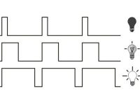
In the previous tutorial we saw how to blink an LED using CloudX board, but in some projects we might need to write to a PORT or a group of pins at the same time. For eg., for designing an 8 LED chaser, writing to pins one after the other makes your code look so bulky but writing to a PORT at once for this kind of projects will make your code look neat and more efficient.
A PORT is a group of pins associated to the same register of a microcontroller. So the controller can control all the pins associated with a particular port at the same time. Usually a 8-bit microcontroller will have 8 bit ports, 16-bit microcontroller have 16 bit ports and 32-bit microcontroller will have 32 bit ports.
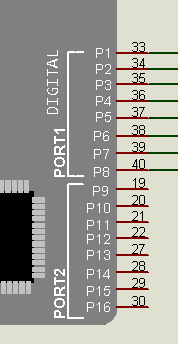
In our case the CloudX microcontroller has 2 ports, PORT1 and PORT2. pin1 to pin8 are associated to PORT1 and pin9 to pin16 are associated with PORT2. Since it is an 8-bit microcontroller we can write to 8 pins at a time.
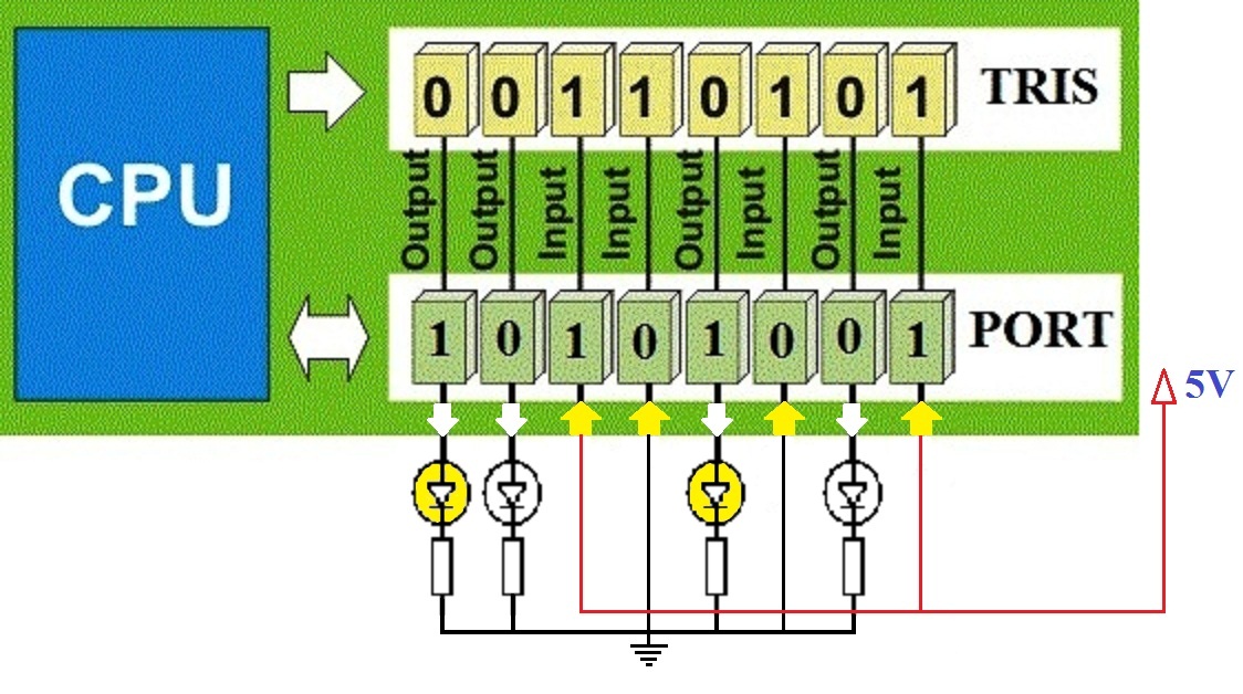
In order to write to PORTs, firstly we need to configure the pins as INPUT / OUTPUT. In this tutorial we are going to write to a PORT and verify it using LEDs. So basically we need to make all pins as OUTPUT pins. So we can use portMode(1, 0b00000000), this will make all 8 pins associated with PORT1 as output pins. For eg. if we use portMode(1, 0b11111111), it will make all pins as INPUTS. The prefix “0b” indicates a binary number.
After that we can write the logic status (HIGH or LOW) to each pins by using portWrite(1, 0b11110000), this will make first 4 pins of PORT1 HIGH and remaining 4 pins as LOW.
In both portMode and portWrite functions, the 1st parameter represents the port you are writing to, while the 2nd parameter represents the data you are writing to the port. For eg. in portMode(1, 0b01001001 ) we are loading the value 0b01001001 to PORT1 for configuration. Thus pin1 (Least Significant Bit) is configured as input and pin2 as output etc.
Components Required
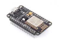
- CloudX Microcontroller Board (Controller and SoftCard)
- LED – 8
- 220Ω Resistors – 8
- Male – Male jumper wires
Circuit Diagram

Programming
#include<CloudX\M633.h>
setup() {
  //setup here
  portMode(1, 0b00000000);
  loop() {
    //Program here
    portWrite(1, 0b11110000);
  }
}
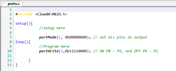
In the code, initially we are setting all PORT1 pins as output using portMode, then we are setting first 4 pins as LOW and remaining 4 pins as HIGH using portWrite. You can feel free to tweak the code to flashing or chasing LEDs.
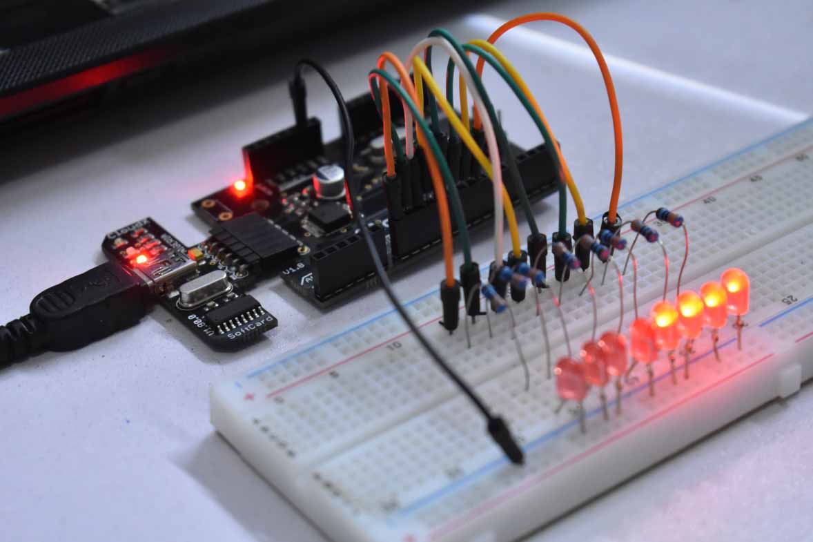
Hardware Experiment


Thanks, I have preferring my legs ahead before two weeks from the day 🙏🙏:
في السبت، 5 جانفي، 2019 16:03، كتب Disqus
what is it all about?
Please, can you help me with my school project?