

Getting Started with CloudX Development Board
Contents
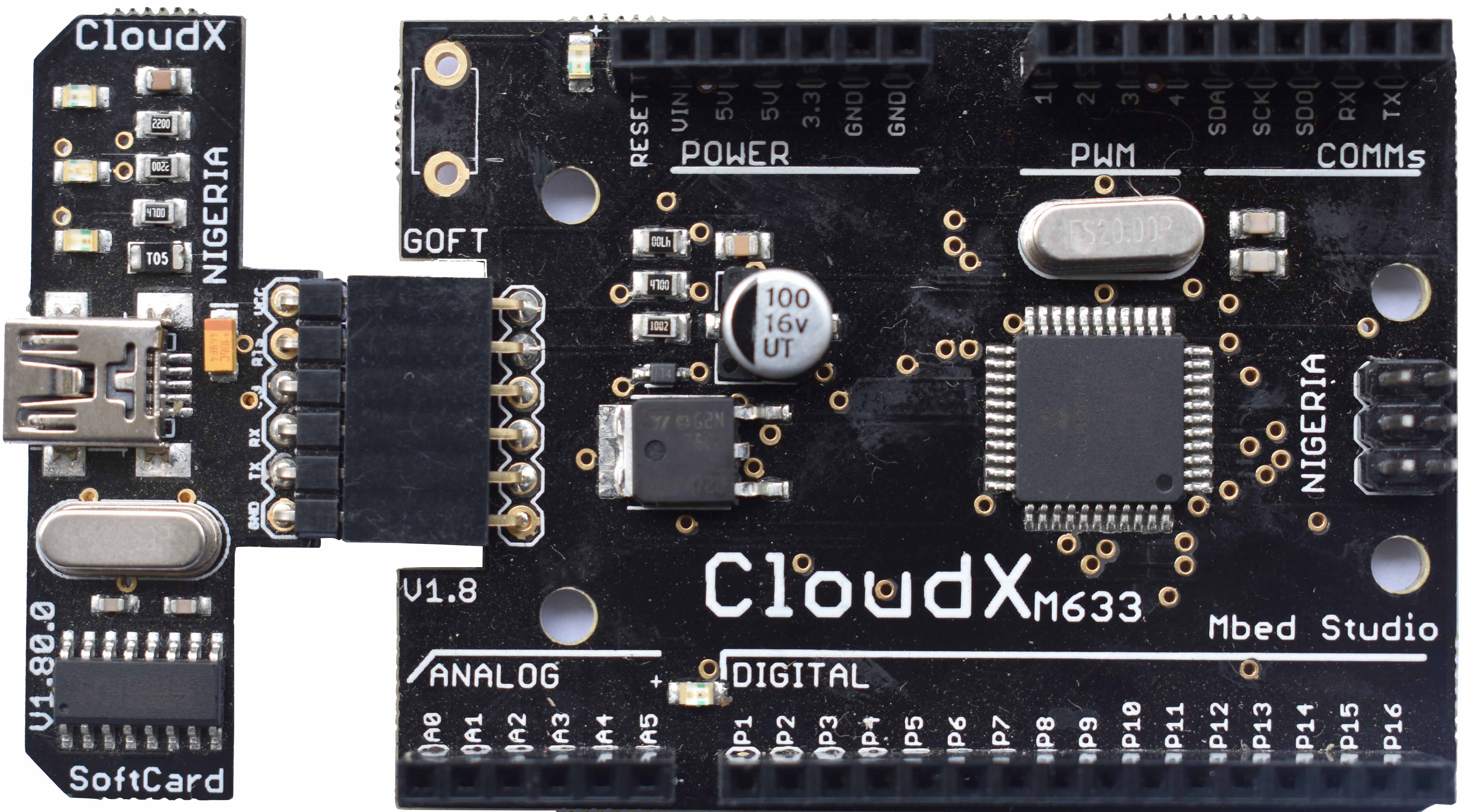
CloudX M633 is one of the popular PIC based microcontroller development board designed by ByteHub Embedded, it comes with over 500 library functions which makes it very easy for beginners to start with embedded systems. In this tutorial we will see how to write our first “Hello World” program to blink an LED using the popular CloudX M633 (PIC16F877A chip) development board.
Components Required
- CloudX Microcontroller Board and SoftCard
- Light Emitting Diode (LED)
- Resistor 220Ω
- 2 male – male jumper wires
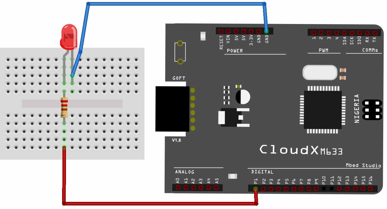
Circuit Diagram
Working
Please note that the CloudX v1.80 comes with an on-board LED connected to P1 so that hobbyist can easily test their first digital output project without any breadboard. The SoftCard serves as hardware programmer that allows users to load their Hex file from computer to the controller board using the CloudX loader software. The positive terminal (Anode +) of the LED is connected to the P1 of the microcontroller through a resistor 220Ω and the negative terminal (Cathode -) of the LED is connected to ground (GND).
In our code, we will turn ON Pin 1 for one second and turn OFF for another one second, the program will keep repeating the loop forever (until the power is on).
Programming
You need to download and install CloudX IDE for this, download link is provided at the end of this article.
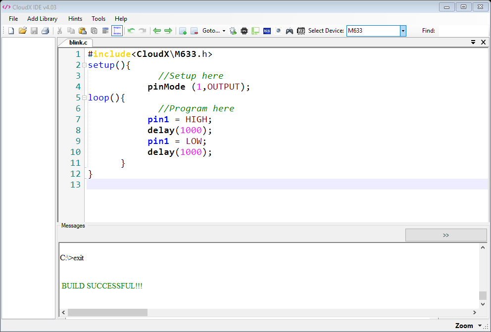
Code
#include <CloudX\M633.h>

setup() {
  //Setup here
  pinMode(1,OUTPUT);

  loop() {
    //Program here
    pin1 = HIGH;
    delay(1000);
    pin1 = LOW;
    delay(1000);
  }
}
In the first part of the program we are initializing the pin P1 as output pin, which means that we can use it for driving LEDs, Transistors, Relays or Buzzers etc. In the second section we are making an infinite loop using loop() and making the pin HIGH and LOW with a delay of 1000 milliseconds. So in effect the connected LED will glow for 1 second and it will turn off for 1 second alternatively.
CloudX IDE
Now let’s compile our project, to do this, click on the ‘Build’ button icon. You will get info about the build process in the ‘Messages’ section. If project is successfully built, then compiler generates files like COFF, Hex, and LST etc., inside the same folder where you saved your project. In case you get ‘Build Failed’ in the messages section then you can scroll up to get hints for possible errors. Hints for errors are always in red in color.
Flashing the program
Once your project build successfully, you can load the hex file (machine code) into the microcontroller board.
Click on the ‘Load’ icon to open the ‘CloudX Loader’. It automatically detects the COM port of the CloudX Board if connected to your computer. Or you can manually select the COM port from the ‘Selected COM Port’ drop down menu.
Click on the Browse button to select the hex file and then Upload button to load the code into the controller. You can see that the LED starts blinking immediately after uploading the code.

Hardware Setup


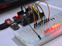


No link for CloudX download.