

Interfacing Matrix Keypad with PIC Microcontroller
Contents
This tutorial explains ‘What is a Matrix Keypad ?’ and ‘How to Interface Matrix Keypad with PIC Microcontroller ?’.
Matrix Keypad
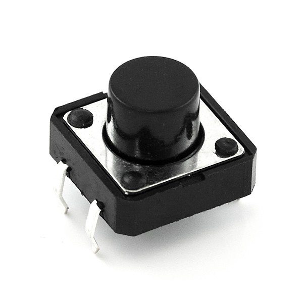
Matrix Keypad is a very useful and userfriendly when we want to design certain applications like Calculator, Telephone etc. Matrix Keypad is made by arranging push button switches in rows and columns. Just imagine, if you want to interface a 4*4 (16 keys) matrix keypad with a microcontroller. In the straight forward way, you will need 16 pins of a microcontroller for that, but by using a simple technique we can reduce it to 8 pins. In the matrix keypad switches are connected in a special manner a shown in the figure below.

Pressed keys can be detected by Scanning. For the sake of explanation, lets assume all column connections (Col1 – Col4) are input pins and all row connections (Row1 – Row4) are output pins. In the normal case (not scanning) all column inputs where in LOW (GND) state. For scanning keypad,
- A Logic HIGH signal is given to Col1 of column inputs.
- Then each Row output (row1 – row4) is scanned one by one. If any of the key belongs to first column is pressed, the Logic high signal from the Col1 will pass to that row. Through we can detect the key.
- This process is repeated for all columns if we want to detect multiple keys.
In this post I am explaining only about detecting one key at a time. For explaining the working I am using a 4*4 matrix keypad and the result is displayed in a Seven Segment Display. Matrix Keypad scanning is stopped as soon as any key press is detected and the Scanning is restarted if we need more inputs.
Interfacing with PIC Microcontroller
Matrix Keypad can also be interfaced with PIC Microcontroller using MikroC Libraries.
Circuit Diagram

Note 1 : VDD and VSS of the pic microcontroller is not shown in the circuit diagram. VDD should be connected to +5V and VSS to GND.
Note 2 : It is highly recommended to add 4 diodes to 4 outputs to the keypad (RB0 ~ RB3) to avoid possible damage to the microcontroller if two keys are pressed simultaneously. For example, in the above circuit if we accidentally press keys 0 and key 1 at the same time, it will short RB0 and RB1 pins of the microcontroller. It will cause higher current consumption when either of the pin is held high during keypad scanning. Thank you “Tim Nicholson” for suggesting this in the comments section.
Matrix Keypad is connected to the PORTB of the PIC Microcontroller. Each column of the Matrix Keypad is connected to RB0 – RB3 of the PIC Microcontroller, which are configured as output pins. While each row of the Matrix Keypad is connected to RB4 – RB7 of the PIC Microcontroller, which are configured as input pins.
Here I am using 4*4 matrix keypad, having characters 0, 1, 2, 3, 4, 5, 6, 7, 8, 9, A, -, C, U, E, F. ‘B’ is replaced by ‘-‘ and ‘D’ is replaced by ‘U’ because Seven Segment Display is used for displaying characters. ‘B’ will be similar to ‘8’ and ‘D’ will be similar to ‘0’ when displayed in Seven Segment Display. For reading data for the Matrix Keypad, each column is made high and rows are scanned as I said above.
MikroC Programming
We use the function readKeyboard() to scan the Matrix Keypad and findKey() to find the pressed key. You can edit the function findKey() to change the character corresponds to each key of the Matrix Keypad.
Function to Scan Keypad
char readKeyboard()
{
 unsigned int i = 0;
 for(i=0;i<4;i++)
 {
  if(i == 0)
  PORTB = 1;
  else if(i == 1)
  PORTB = 2;
  else if(i == 2)
  PORTB = 4;
  else if(i == 3)
  PORTB = 8;

  if(PORTB.F4)
    return findKey(i,0);
  if(PORTB.F5)
   return findKey(i,1);
  if(PORTB.F6)
   return findKey(i,2);
  if(PORTB.F7)
   return findKey(i,3);
 }
 return ' ';
}
This function initiates the keypad scanning and returns the character corresponds to the pressed key when a key press is detected. It uses the function findKey() to find the character corresponds to a particular row and column. In this function space (‘ ‘) is used as the null character, which is returned when no key is pressed, you may change this according to your needs.
Function to Find Keys
char findKey(unsigned short a, unsigned short b)
{
 if(b == 0)
 {
   if(a == 3)
    return '0';
   else if(a == 2)
    return '1';
   else if(a == 1)
    return '2';
   else if(a == 0)
    return '3';
 }
 else if(b == 1)
 {
   if(a == 3)
    return '4';
   else if(a == 2)
    return '5';
   else if(a == 1)
    return '6';
   else if(a == 0)
    return '7';
 }
 else if(b == 2)
 {
   if(a == 3)
    return '8';
   else if(a == 2)
    return '9';
   else if(a == 1)
    return 'A';
   else if(a == 0)
    return '-';
 }
 else if(b == 3)
 {
   if(a == 3)
    return 'C';
   else if(a == 2)
    return 'U';
   else if(a == 1)
    return 'E';
   else if(a == 0)
    return 'F';
 }
}
This function returns the character corresponding to a particular row and column. You may change characters corresponding to each key according to your need by editing this function.
Seven Segment Decoding Function
unsigned int sevenSegmentDecoder(char a)
{
 switch(a)
 {
   case '0': return 0x3F;
   case '1': return 0x06;
   case '2': return 0x5B;
   case '3': return 0x4F;
   case '4': return 0x66;
   case '5': return 0x6D;
   case '6': return 0x7D;
   case '7': return 0x07;
   case '8': return 0x7F;
   case '9': return 0x6F;
   case '0': return 0x3F;
   case 'A': return 0x77;
   case '-': return 0x40;
   case 'C': return 0x39;
   case 'U': return 0x3E;
   case 'E': return 0x79;
   case 'F': return 0x71;
   case ' ': return 0;
 }
}
This function decodes the given character to display it in Seven Segment Display.
Reading Multiple Pressed Keys at a Time with PIC Microcontroller
You can download the MikroC Source Code, Proteus files etc here…


It is not there in the circuit diagram. It is better to add 4 diodes to 4 outputs to the keypad (RB0 ~ RB3) but things will work fine without that. It is just an additional protection.
Hi. I cannot see the diodes, or or how they are connected in the diagram. Can you please clarify>
Regards.
Thank you very much for your valuable suggestion. Actually I didn’t even thought about this situation.
Even though I don’t want to complicate the circuit here as this is purely intended for hobbyists/students. I added a note below the circuit diagram adding these points. https://electrosome.com/matrix-keypad-pic-microcontroller/#Circuit_Diagram
I really appreciate your help.
Hi Ligo,
You need to add diodes to the four outputs from the micro. With your current design, it is possible to put a short across the micro by simply pressing two buttons at the same time.
For example of you press both button 1 and button 2 at the same time you effectively join RB1 and RB2 together (follow the current path). When scanning RB1 you are driving it high while driving RB2 low, that results in a short circuit which will cause high current to flow through the port; this is likely to damage it permanently. Even if the micro has short circuit protection, it is bad practice to design any circuit that relies on such protection for normal operation. On many microcontrollers your circuit will simply destroy the output port if the user were to accidentally press two keys together.
or use a Texas Instruments TIL311 HEX LED display.
the function findkey(unigned short a, unsigned short b)
is it the same by saying findkey(usigned short row, unsigned column) or probably findkey(usigned short column, unsigned row)???
Yes, just turn on the led if it matches a particular key.
How may I use this matrix key to make on and off the led.
It is assembly language coding.
is there anyone can code like this? HELP ME PLEASE ASAP!
I CANT UNDERSTAND THIS CODES…https://uploads.disquscdn.com/images/1dba773e931240026ddc0d9803a1fa13f8497e8489dc5683357dfb9972bbcc68.png
if(PORTB.F4) is same as if(PORTB.F4 == 1)
In readKeyBoard function,there is state that { if(PORTB.F4) }..i dont understood the meaning of that.because that’s no condition..the condition is like this {if(PORTB.F4== 0)}…Please help me
Interesting tutorial. You could use b and d as minuscles, thus you can represent them in the 7-seg display, instead of using – and U. This will be more intuitive.
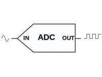
Yes… by using analog to digital converter… search for it..
Very helpful article. Is there any other way rather than continuous scanning?
http://www.electrosome.com/lcd-pic-interfacing/
give me more explanation abt lcd commands