Interfacing PIR Motion Sensor with Arduino
Contents
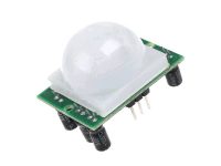
A PIR sensor is generally known to the world as a motion sensor or motion detector. So in this project we are going to use the PIR motion sensor to detect motion. Here we are going to sense movement of human by using Passive infrared sensor (PIR sensor). Using the feedback from the sensor we will control an LED with the help of Arduino Uno.
Components Required
- Arduino Uno
- PIR Sensor
- 330Ω Resistor
- LED
- Breadboard
- Connecting Wires
Hardware
Circuit Diagram
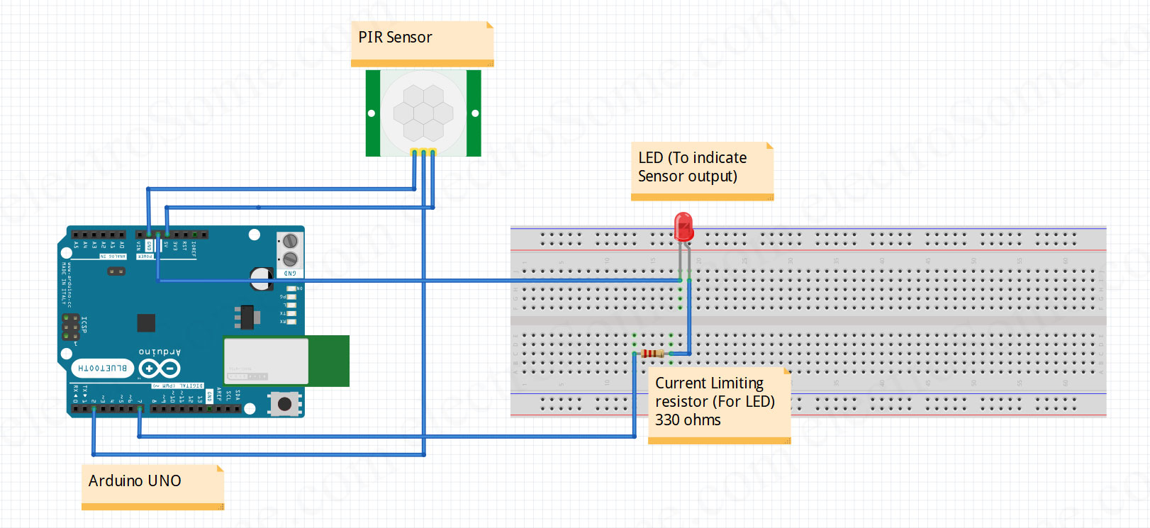
Circuit Explanation
Connection between PIR Sensor and Arduino
- Connect first (GND) pin of PIR Sensor to GND pin of Arduino
- Connect second (Vout) pin of PIR Sensor to digital pin 2 of Arduino
- Connect third (Vcc) pin of PIR Sensor to 5V pin of Arduino
Connection between LED and Arduino
- Connect positive terminal of LED to one lead of the resistor.
- Connect other lead of the resistor to digital pin 7 of Arduino
- Connect negative terminal of LED to GND pin of Arduino
Software
There are two programming approaches for interfacing of PIR motion sensor with Arduino as below.
Polling Method
In this method the microcontroller continuously executes the loop and checks the status of the input pin on which the sensor is connected.
It is an inefficient method as the microcontroller is kept constantly busy and hence cannot perform any other task. And it also results in more power consumption.
void setup() // Put your setup or configuration code in the setup function, it will only run once during the startup.
{
  pinMode (7,OUTPUT); // Initialize digital pin 7 as an output.
  pinMode (2,INPUT); // Initialize digital pin 2 as an input.
}

void loop() //Put your main code in void loop() function to run repeatedly.
{
  int i=digitalRead(2); // Reads the digital pin 2 of Arduino
  if (i==1)             // Checks for motion detection.
  {
    digitalWrite(7, HIGH); // If motion detected, turns ON the LED which is connected to digital pin 7.
  }
  else
  {
    digitalWrite (7, LOW); // If motion not detected then turns OFF the LED which is connected to digital pin 7.
  }
}
Interrupt Method
In this method we set up the arduino in the interrupt mode. So the microcontroller does not need to continuously check the status of the input pin to which the sensor is connected.
The microcontroller can continue doing other tasks in the loop. When there is a signal on the sensor pin, an interrupt is generated. Which triggers the microcontroller to execute the Interrupt Service Routine (ISR). The ISR is the code that will be executed when an interrupt is encountered.
ISRs are special kinds of functions that have some limitations unlike normal functions. For eg. an ISR cannot have any parameters and they cannot return anything
After the ISR is executed, the controller will resume back to the main loop and continue it’s job.
This is an efficient method as it does not make the microcontroller busy all the time and also helps to conserve some power consumption.
In Arduino Uno we have two interrupt input pins, Pin No. 2 and Pin No. 3. Hence we have connected the sensor output to the Pin No 2 which shall cause the interrupt.
The interrupt can be configured in 3 modes:
- RISING : The interrupt will be caused when a rising edge of signal is encountered i.e signal goes from LOW to HIGH.
- FALLING : The interrupt will be caused when a falling edge of signal is encountered, i.e signal goes from HIGH to LOW.
- CHANGE : The interrupt will be caused when a rising or a falling edge is encountered, i.e if is any change in the signal status (Interrupt is caused when signal goes from “LOW to HIGH” and “HIGH to LOW”).
volatile boolean pirState = 0; // Initialize the variable with 0 value.
void setup()  // Put your setup or configuration code in the setup function, it will only run once during the startup.
{
  pinMode(13, OUTPUT); // Initialize digital pin 13 as an output.
  pinMode(2, INPUT);   // Initialize digital pin 2 as an input.
  attachInterrupt(digitalPinToInterrupt(2),pirResponse,CHANGE ); // This command is used to set PIN 2 in interrupt mode on arduino. pirResponse is the ISR (code that will be executed when interrupt is raised).
}

void loop() // Put your main code in void loop() function to run repeatedly.
{
}

voidpirResponse() // Function to moniotr the detection motion.
{
  if (pirState==1) // Monitors the status of variable
  {
    pirState=0;  // Makes pirstate to 0 in order to proceed for further process.
    digitalWrite(13,LOW); // If motion not detected then turns OFF the LED which is connected to digital pin 7.
}
  else
  {
    pirState=1;  // Makes pirState to 0 in order to proceed for further process.
    digitalWrite(13,HIGH); // If motion detected then turns ON the LED which is connected to digital pin 7.
  }
}
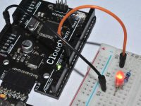
Practical Implementation

Working
This project uses PIR sensor to sense the motion (movement) of human being and turns ON an LED to indicate about the detection of motion. Movement of human will be detected by the PIR sensor. PIR Sensor provides a triggering pulse to arduino. Arduino generates output at Pin No. 7 to turn ON the LED.