

Expanding IO Ports of PIC Microcontroller using MCP23S17
Contents
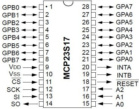
Usually a microcontroller comes with a limited number of IO ports called General Purpose Input Output (GPIO) ports. But some applications require more IO ports than that available on a microcontroller. In these cases we can use IO Port Expanders to increase the IO capability of a microcontroller. MCP23017 and MCP23S17 are two such 16 bit IO expander with Serial Interface manufactured by Microchip. MCP23017 uses high speed I2C interface while MCP23S17 used high speed SPI interface.

In this tutorial we will see how to expand IO ports of a PIC Microcontroller using MCP23S17. MikroC Pro for PIC Microcontroller provides built in libraries to communicate with MCP23S17 via SPI interface. We can connect up to eight MCP23S17 on a SPI Bus by using the three address pins present on it.
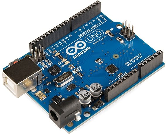
In this example project we use PIC 16F877A to demonstrate the working of MCP23S17. PORTA and PORTB of MCP23S17 is configured as Input and Output respectively. SPST switches are connected to PORTA along with the internal PULL UP of MCP23S17 and LEDs are connected to PORTB via current limiting resistors. Input to PORTA is the output to PORTB, so LEDs connected to PORTB will GLOW according the the status of SPST switches connected to PORTA.
Circuit Diagram – IO Port Expanding PIC Microcontroller

Note: VDD , VSS of the PIC Microcontroller and MCP23S17 are not shown in the circuit diagram. VDD should be connected to +5V and VSS to OV.
When a switch is ON corresponding LED will be OFF and when a switch is OFF corresponding LED will be ON. Since all the three address pin of MCP23S17 are grounded its address is 0.
MikroC Library Functions
- void Expander_Init(char address) : To initialize the IO Port Expander using SPI Communication.
- char Expander_Read_Byte(char address, char RegAddress) : To read a byte from Port expander using the internal register address.
- void Expander_Write_Byte(char address, char RegAddress, char Data) : To write a byte to Port Expander.
- char Expander_Read_PortA(char address) : To read a byte from Port Expanders Port A.
- char Expander_Read_PortB(char address) : To read a byte from Port Expanders Port B.
- unsigned int Expander_Read_PortAB(char address) : To read a word from Port Expanders Port A and Port B. Port A reading are in the higher byte of result and Port B readings are in the lower byte of result.
- void Expander_Write_PortA(char address, char Data_) : To write a byte to Port Expanders Port A.
- void Expander_Write_PortB(char address, char Data_) : To write a byte to Port Expanders Port B.
- void Expander_Write_PortAB(char address, unsigned int Data_) : To write a word to Port Expanders Ports A and B.
- void Expander_Set_DirectionPortA(char address, char Data_) : To set the direction of each pin of Port A. This function writes data to Port A’s direction register similar to TRIS register in PIC.
- void Expander_Set_DirectionPortB(char address, char Data_) : To set the direction of each pin of Port B.
- void Expander_Set_DirectionPortAB(char address, unsigned int Direction) : To set the direction of each pin of Port A and Port B of Port Expander. Higher byte is for Port A Direction regiter while lower byte is for Port B Direction Register.
- void Expander_Set_PullUpsPortA(char address, char Data_) : To setup internal Pull Up or Down resistors for Port A. Data is used for choosing Pull Up/Down, setting a bit corresponds to setting Pull Up resistor for corresponding pin of Port A.
- void Expander_Set_PullUpsPortB(char address, char Data_) : To setup internal Pull Up or Down resistors for Port B.
- void Expander_Set_PullUpsPortAB(char address, unsigned int PullUps) : To setup internal Pull Up or Down resistor for Port A and Port B of Port Expanders. As in the above cases higher byte is for Port A and lower byte is for Port B.
Note : Port Expander Module connections should be declared before the main functions as shown in the following example. SPI Module and Port Expander should be initialized before using other functions.
MikroC Code
// Port Expander module connections
sbit  SPExpanderRST at RC1_bit;
sbit  SPExpanderCS  at RC0_bit;
sbit  SPExpanderRST_Direction at TRISC1_bit;
sbit  SPExpanderCS_Direction  at TRISC0_bit;
// End Port Expander module connections

void main()
{
  int a;
  SPI1_Init();               // Initialize SPI module used with PortExpander
  Expander_Init(0);          // Initialize Port Expander at address 0

  Expander_Set_DirectionPortA(0, 0xFF); //All pins on PORTA as Inputs
  Expander_Set_DirectionPortB(0, 0x00); //All pins on PORTB as Outputs

  Expander_Set_PullUpsPortA(0, 0xFF);  //Setting Internal Pull Ups for PORTA

  do
  {
     a = Expander_Read_PortA(0);  //Reading Data from PORTA
     Expander_Write_PortB(0, a);  //Writing Data to PORTB
     Delay_ms(100);
  }while(1);
}
You can download the hex file, MikroC source code, Proteus files etc here…


hi
how can ı make this button starts and stops pls help me
thks
hi
how can ı make it start stop button in this code thks
Try this link : http://electrosome.com/expanding-output-pins-pic-microcontroller-multiplexing/
Dear Sir,
I Want to Extend my Port as Output Only. Is it Possible to Configure my ports as Output? Also I want to use multiple MCP23S17 in single Bus, Is it Possible?.