

Arduino Uno
Contents
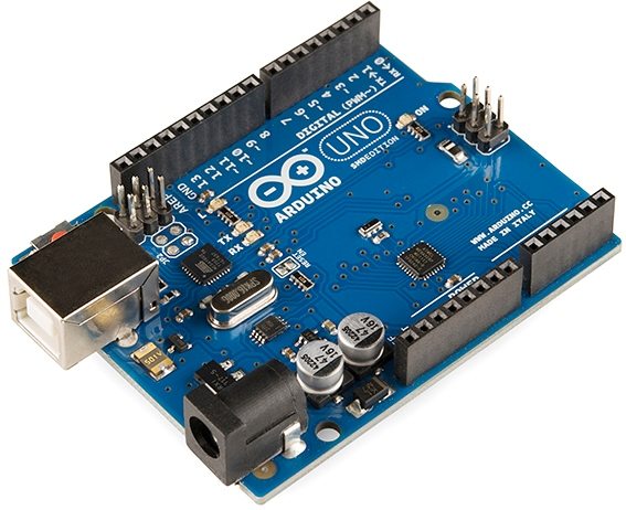
The Arduino Uno is the most popular one among other Arduino development boards. It is based on the microcontroller ATmega328. The factor which make Arduino Uno differ from others is that it does not use FTDI USB-to-serial driver chip. Instead it uses a microcontroller Atmega16U2 (Atmega8U2 up to version R2) which is programmed as USB-to-serial converter. Its peripheral features includes 14 digital input/output pins (of which 6 can provide PWM outputs), 6 analog inputs, a 16MHz crystal oscillator, a USB connector, a power jack, an ICSP header and a reset button.
We can power Arduino Uno in 2 different ways, either by USB connection or by using an external power supply. AC-DC adaptor and battery will come under the category of external power supply. To use battery, connect its leads to the Vin and GND pins on the board. To use adaptor, connect a 2.1mm center positive plug in to the board’s power jack. The board can operate in the range of 6-20V of the external power source. But the most suitable range is 7-12V. If the input voltage is less than 7V, the on-board regulator can’t produce proper regulated 5V and the board will become unstable. If the input voltage is more than 12V it will cause the voltage regulator to be overheated and may result in damaging the board.
Arduino can be programmed using Arduino Software. Make sure that you are selected Arduino Uno in the Tools >> Board menu. User need to define only two functions setup() and loop(). Where setup() is the preparation and loop() is the operation. Sketch is the term used to indicate program or code written for Arduino. After writing the sketch, simply click the upload button in the Arduino environment for writing the code to the Arduino. After writing the code automatic reset will be happen, so the physical pressing of the reset button is not required.
All the 14 digital pins of Arduino can be used as input as well as output. pinMode(), digitalWrite() and digitalRead() are the functions used for this purpose. pinMode() is the function used for setting the direction a digital pin, ie Input or Output. digitalWrite() is the function used to write value to an output pin, ie HIGH or LOW. Similarly digitalRead() is a function, which reads the status of an input pin. Each pin has internal pull up resistor of 20 – 50KΩ which is disconnected by default.
Arduino Uno can be used for the serial communication with other microcontrollers or computers or with other Arduino boards. The digital pins 0 (Rx) and 1 (Tx) can be used for this communication which is provided by ATmega328 microcontroller on the board. Note that the Rx and Tx LEDs on the board will not indicate the serial communication through pin 0 and 1 but it will flash when data being transmitted via the USB-to-serial chip and USB connection to the computer.
ATmega 328 has 32KB of flash memory for storing the program. 2KB of SRAM and 1KBof EEPROM are also available. Arduino Uno provides an external polyfuse for the protection of the computer’s USB. The fuse will break automatically when more than 500mA of current passed to the USB port and it will remain until the short or overload is removed.
Technical Details – Arduino Uno
| Microcontroller | ATmega328 |
| Operating Voltage | 5V |
| Clock Speed | 16MHz |
| Input Voltage Range (On-Board Regulator) | 6 – 20V |
| Recommended Input Voltage Range | 7 – 12V |
| Digital Input Output Pins | 14 (6 can provide PWM output) |
| Max. Current per IO pin | 40mA |
| Max. Current for 3.3V pin | 50mA |
| Analog Input Pins | 6 |
| Flash Program Memory | 32KB (of which 0.5KB is used by bootloader) |
| SRAM | 2KB |
| EEPROM Data Memory | 1KB |
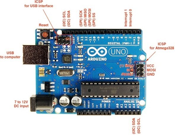
Pin Details – Arduino Uno
|
|
|
| IOREF (only in R3) | Input Output voltage reference pin, it is internally connected to 5V. Arduino Shields can read this pin to see the board is running at 3.3V or 5V. This allows it to select proper power source or enable input output voltage translators for proper working. |
|---|---|
| RESET | This pin can be used to RESET arduino. LOW voltage level at this pin resets arduino which is similar to pressing RESET button. |
| 3.3V | 3.3V Output |
| 5V | 5V Output |
| GND | Reference Ground |
| Vin | External Power Input. You may connect +ive of the battery to this pin and -ive of the battery to GND. |
| A0 – A5 | Analog Voltage Input Pins |
| AREF | Analog Voltage Reference Input. By default analog to digital converter reference voltages are 0 and 5V. We can change the higher reference voltage 5V using AREF pin and analogReference() function. |
| 0 – 13 | Digital Input Output Pins |
| ~ | Indicated PWM Outputs |
| TX & RX | Transmit and Receive pins of UART. |
Schematic Diagram
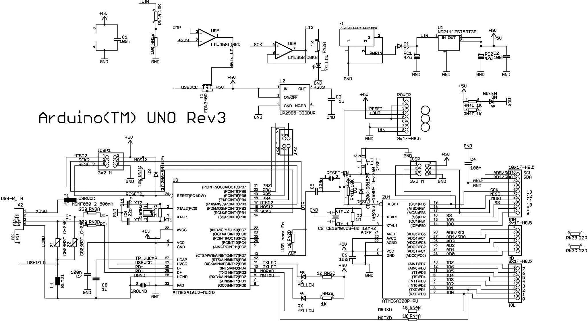
You can find more details on the Arduino Website.
