

FM Generation using 555 Timer
Contents
In communication systems, Frequency Modulation (FM) is the process in which information (message signal) is transmitted over a carrier wave by varying its instantaneous frequency. The difference between instantaneous frequency and central frequency of the carrier will be directly proportional to the instantaneous value of the amplitude of message signal. 555 Timer wired in Astable Mode can be used for generating Frequency Modulated (FM) waves. Please read the article Astable Multivibrator using 555 Timer for more details about the circuit. In astable multivibrator we don’t use the 5th (Control Voltage) pin of 555 but here we fed the message signal to this pin which results in the variation of frequency.
Circuit Diagram

8th and 1st pin of the 555 are used for giving power, Vcc and GND respectively. 4th pin is the Reset pin which is a active low input, since it is tied to Vcc. When the output is high, capacitor C1 charges to Vcc through R1 and D. When the output is low, capacitor discharges through resistor R2 and 7th of the IC. This charging and discharging time periods determines the time period of output. Message signal is fed to 5th (Control Voltage) pin of the IC through a coupling capacitor and the output can be taken from the 3ed pin of the IC.
Working
I hope that you read the working of Astable Multivibrator using 555 Timer. Central frequency or Carrier frequency of the generated FM can be determined from the expression, fo = 1/(1.4RC), where R = R1 = R2 and C = C1.
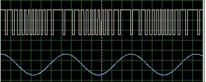
When an input voltage (say V) is given to Control Voltage pin, the upper and lower comparator reference changes to voltages V and V/2. So when the capacitor voltage becomes less than V/2, output becomes high and the capacitor starts charging to Vcc through resistor R1 and diode D. When the the capacitor voltage becomes greater than V, output becomes low and the capacitor starts discharging through resistor R2 and 7th pin of the IC. So the time period is proportional to the input voltage V. So as V increases, time period of the output wave increases and when V decreases time period of the output wave decreases.
Output
Design
- fo = 1/(1.4RC), where R = R1 = R2 and C = C1
- Coupling capacitor C3 is designed in such a way that it can couple the input message signal.
You can use our 555 Astable Multivibrator Calculator in the bottom of the article Astable Multivibrator using 555 Timer for easy calculations.


Hi there, thank you for the project but I have a problem
I made the circuit correctly and used the right capacitors and resistors with the right values but it didn’t work, I even checked the connections and there were no problems, I also tried every single FM wave from 87.5 to 108 and none of them worked, and I connected a antenna as well but no hope, can you help me please, thank you.
(By the way I used a 10uF 50V electrolytic capacitor if that matters, the 0.1uf capacitor is ceramic)
(something else, can i put a microphone at the input signal?)
Shouldn’t frequency be 1/(0.693*2*R*C)? The period is 2*0.693*R*C (As we are first charging and then discharging through the RC).
It should be in the Range 88 to 108MHz, but 555 will not work on that range.
what will be the frequency of modulation so i tuned my moble radio …sir!
ya u can give 4 volt also
Please give me more details like the following.
1. Input Voltage
2. Input Frequency
3. How are you checking the output etc..
lo arme igual que el diagrama y no logro conseguir la modulacion de FM, que frecuencia y amplitud debe tener la senl moduladora?
Yes.
Check the frequency limits of 555.
Can the input signal be smaller than 5V p-p??
Given the formula for oscillating frequency, by varying the values of R and C, it’s possible to get f in range of 88 to 108Mhz right?
yes.. variable frequency.
please tell me variable frequency or not. if it is variable please tell me range
its 42 its always 42
what is the maximum carrier frequency we can generate using 555
Try using any fm demodulators..
but how demodulate this signal ?
That is not a good idea…. For generating frequency modulated sine wave.. you should try a different circuit……. Use a sine wave oscillator with.. a varactor diode..
Is there a way to convert the modulated square wave to a modulated sinusoidal wave?
Can you use a sharp low pass filter?
NOP………..
But we can produce frequency modulation….
@ Abhay – will the 555 oscillate in the 88 to 108 Mhz range ?
No, you can’t make a demodulator using 555..
Yes….
And is there any way to make a Demodulator(receiver) using 555???
ok…can i directly connect an antenna at pin3
I think you need external antenna.. It depends on the frequency of carrier..
WILL PIN 3 WORK AS ANTENNA??