

Generating PWM with PIC Microcontroller using CCP Module
Contents
PWM is a technique used to generate analog output signal using digital signals. It is commonly used to control average power delivered to a load, motor speed control, generating analog voltage levels and for generating analog waveforms.
CCP Modules are available with a number of PIC Microcontrollers. CCP stands for Capture/Compare/PWM. Using PWM module is far more easier and cost effective than using extra chips for PWM generation. MikroC Pro for PIC Microcontroller provide built-in library for PWM which makes our task very simple.
MikroC Functions
- PWM1_Init(constant long frequency) : This function initializes the PWM module with duty ratio 0. Frequency parameter is the desired frequency in Hz. It should be a numeric constant, should not be a variable.
- PWM1_Set_Duty(unsigned short duty_ratio) : This function is used to set the duty cycle of the PWM. The parameter duty_ratio takes values from 0 to 255, ie 0 means 0% , 127 means 50% and 255 means 100% duty cycle. The PWM1_Init() routine must be called before using this.
- PWM1_Start() : This function starts the PWM output. PWM1_Init() must be called before calling this routine,
- PWM1_Stop() : This function stops the PWM output. PWM1_Init() must be called before calling this routine. PWM1_Start() should be called before calling this function otherwise calling this function will not have any effect as PWM module is not running.
Note 1 : For microcontrollers with more than one CCP module, to use the desired CCP module for PWM generation simply change the number “1” in the prototype with desired module number. eg: PWM2_Init(5000), PWM2_Start().
Note 2 : All PWM modules in a PIC Microcontroller uses Timer 2 for its operation, so you cannot set different frequencies for different PWM modules.
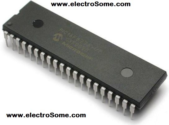
In this tutorial we are using PIC 16F877A for demonstrating PWM generation using CCP module. PIC 16F877A contains two CCP modules.
Circuit Diagram – Using internal PWM Module of PIC
In the below circuit four switches are provided for controlling the Duty Ratio of PWM generated by two CCP modules of the PIC Microcontroller.
- Switch 1 : To increase the Duty Ratio of PWM produced by CCP1
- Switch 2 : To decrease the Duty Ratio of PWM produced by CCP1
- Switch 3 : To increase the Duty Ratio of PWM produced by CCP2
- Switch 4 : To decrease the Duty Ratio of PWM produced by CCP2

The output of the two CCP modules are given to a CRO to observe the changes in pulse width. It may be given to two LEDs and you can see the changes in brightness as Duty Ratio changes.
MikroC Program
void main()
{
  short current_duty_1  = 16; // initial value for current_duty_1
  short current_duty_2 = 16;  // initial value for current_duty_2

  TRISD = 0xFF; // PORTD as input
  TRISC = 0x00; // PORTC as output

  PWM1_Init(5000);  // Initialize PWM1
  PWM2_Init(5000);  // Initialize PWM2

  PWM1_Start();  // start PWM1
  PWM2_Start();  // start PWM2

  PWM1_Set_Duty(current_duty_1); // Set current duty for PWM1
  PWM2_Set_Duty(current_duty_2); // Set current duty for PWM2

  while (1)        // endless loop
  {
     if (!RD0_bit)   // if button on RD0 pressed
     {
      Delay_ms(40);
      current_duty_1++;  // increment current_duty_1
      PWM1_Set_Duty(current_duty_1);  //Change the duty cycle
     }

    if (!RD1_bit)               // button on RD1 pressed
    {
      Delay_ms(40);
      current_duty_1--;  // decrement current_duty_1
      PWM1_Set_Duty(current_duty_1);
     }

    if (!RD2_bit)     // if button on RD2 pressed
    {
      Delay_ms(40);
      current_duty_2++;    // increment current_duty_2
      PWM2_Set_Duty(current_duty_2);
     }

    if (!RD3_bit)       // if button on RD3 pressed
    {
      Delay_ms(40);
      current_duty_2--;   // decrement current_duty_2
      PWM2_Set_Duty(current_duty_2);
     }

    Delay_ms(10);      // slow down change pace a little
  }
}
I thinks the program is self explanatory, so if you have any doubts please comment below…
Download
You can download the MikroC Source Code, Proteus files etc here…


Thanks for helping others.
current_duty_1–; => wrong
current_duty_1––; => true
HI,
I have programmed the pic16f88 the below program. Pin RA0 & RA1 are connected to 2 push buttons for increment or decrement the Pwm & Pin RB0 is used for ccp1 out & connected to Led . After powering the circuit i can see the pwm on RB0 Led and on scope also but no change happens after pushing 2 push buttons … Can you please help ? Internal Oscillator frequency is set to 8 Mhz.
void main()
{
short current_duty_1 = 16; // initial value for current_duty_1
TRISA = 0xFF; // PORTA as input
TRISB = 0x00; // PORTB as output
PWM1_Init(5000); // Initialize PWM1
PWM1_Start(); // start PWM1
PWM1_Set_Duty(current_duty_1); // Set current duty for PWM1
while (1) // endless loop
{
if (!RA0_bit) // if button on RD0 pressed
{
Delay_ms(40);
current_duty_1++; // increment current_duty_1
PWM1_Set_Duty(current_duty_1); //Change the duty cycle
}
if (!RA1_bit) // button on RD1 pressed
{
Delay_ms(40);
current_duty_1–; // decrement current_duty_1
PWM1_Set_Duty(current_duty_1);
}
Delay_ms(10); // slow down change pace a little
}
}
hello sir can we use this code for half bridge mosfet driver
Sir our thesis is all about buck-boost converter using pic16f877a..can you help me how to use the pins on that microcontroller so that the switch of our microcontroller is that pic
Do you know how to generate SPWM with a TI microcontroller?
Please help me…i want to control light brightness by using PIC Micro
controller with button (PWM)..I found this in your site. Why my LED
always blinking…in oscillation PWM working. Please give me a proper
solution or give me a source code for light brightness control PIC with
push buttons
in which software i do the programming
how to generate 3 different delayed pulses to switch on 3 mosfets in micro c?
.
Do anybody have a code for PLECS [C-subscript] for PWM generation of three phase induction motor?
void main() {
TRISC.F2=0;
TRISC.F1=0;
T2CON.T2CKPS1=0;
T2CON.T2CKPS0=1;
PR2=0XF9;
CCP1CON.CCP1M3=1;
CCP1CON.CCP1M2=1;
CCP1CON.CCP1M1=0;
CCP1CON.CCP1M0=0;
CCPR1L=0X52;
CCP1CON.CCP1X=0;
CCP1CON.CCP1Y=0;
T2CON.TMR2ON=1;
DELAY_us(250);
T2CON.T2CKPS1=0;
T2CON.T2CKPS0=1;
PR2=0XF9;
CCP2CON.CCP2M3=1;
CCP2CON.CCP2M2=1;
CCP2CON.CCP2M1=0;
CCP2CON.CCP2M0=0;
CCPR2L=0X52;
CCP2CON.CCP2X=0;
CCP2CON.CCP2Y=0;
T2CON.TMR2ON=1;
while(1);
}
this is the code and i am getting two PWM without delay
sir how can i produce two pwm signals with same duty cycle and a delay between two using mikroC I tried and i am not able to give delay
I need code for PIc18
Hi dear George,first of all thank you,sir i need to 3 phase pwm for 3 phase inverter progect with 120 and 240 degree phase shift?can you help me?
regards
You may use normal delay functions or timer interrupt for that.
sir, i have to generate a pulse of 2 second period and 50 % duty cycle in pic16f877a having clock frequency is 8 mhz. please help…
Yes,
Can we generate 50kHz PWM signal using PIC16F883?
It should not happen like that. Try using the latest version of MikroC.
when i use PWM2_Stop() the PWM1 stop also. Why ?
Hello Sir,
Please tell me is it possible to generate staircase waveform using PWM in PIC32??
Yes, ofcourse.
Hey, I am making SPIM using micro controller, So can I provide pulses to my inverter with this (16F877A) micro controller?
Sorry, I don’t have any codes for inverter.
hello sir thank you for you share this with us.. for inverter i am using spwm technique for 1Khz carrier frequency. and pic16f886 chip. can you plz help me in cooding for this converter.?
hello sir thank you for you share this with us.. for inverter i am using spwm technique for 1Khz carrier frequency. and picf16f**& chip. can you plz help me in cooding for this converter.?
You can generate a soft PWM using CCP PWM interrupt. You can add delay there. But both PWMs will have same frequency.
I am new to PIC and I would like to use it to make 2 PWM signals that are shifted. Is there a standard command/way to do this?
I think it is 5MHz
I hope that you can use above PWM method for controlling the speed of dc motor.
sir ligo, how can i control the speed of two dc water pump… one for inlet and one for outlet.. im using pic16f877a with ultrasonic as a sensor… i need it asap for my final year project…
i appreciate it if u help me 🙂
Yes, you can use the same code.
hi sir am new to mikro c compiler,in eariler am using mplab and ccs compilier. i need to pwm program for pic18f66k80 how can i use the same code for that ic please tell me . thanks in advance
#include
#use delay (clock = 20000000)
#fuses hs,nowdt,nobrownout,noprotect
#byte PORTB=0xF81 //port B will be used as output
#byte PORTC=0xF82 //port C also will be used as output
#byte PORTD=0xF83//port D as input 12V
void main()
{
set_tris_d(1);//set portD as input connected to pin 12V
set_tris_b(0); //set portB as output. portB set as ccp1 connected to green light.
set_tris_c(0);//set portD as output. c1 and c3 connected to red and blue.
setup_ccp1(ccp_pwm); // set ccp1 as pwm
setup_timer_2(T2_DIV_BY_16,225,1); //set timer2 divisian 255,internal as 1
while(1)
{
if(input(pin_d0))
{
output_high(pin_b3); //to ON enable
output_high(pin_c1); //to make led move forward
output_low(pin_c2); //when input b0 is high
set_pwm1_duty(150);//at 7.03v
set_timer2(0);
delay_ms(40);
set_pwm1_duty(175);//at 8.20v
set_timer2(0);
delay_ms(40);
set_pwm1_duty(200);//at 9.44v
set_timer2(0);
delay_ms(40);
set_pwm1_duty(225);//at 10.55v
set_timer2(0);
delay_ms(40);
set_pwm1_duty(250);//at 11.72v
set_timer2(0);
delay_ms(40);
set_pwm1_duty(255);//at 11.96v
set_timer2(0);
delay_ms(40);
}
else
{
output_high(pin_b3);//to on enable
output_low(pin_c1);//to make led move backward
output_high(pin_c2);//when input b0 is low
set_pwm1_duty(150); //at 7.03v
set_timer2(0);
delay_ms(40);
set_pwm1_duty(175);//at 8.20v
set_timer2(0);
delay_ms(40);
set_pwm1_duty(200);//at 9.44v
set_timer2(0);
delay_ms(40);
set_pwm1_duty(225);//at 10.55v
set_timer2(0);
delay_ms(40);
set_pwm1_duty(250);//at 11.72v
set_timer2(0);
delay_ms(40);
set_pwm1_duty(255);//at 11.96v
set_timer2(0);
delay_ms(40);
}
}
}
i dunno what happen, but when i attached to my 9v battery, they only give red color..
What is the maximum switching frequency I can achieve using PIC16F877A
Yes.. ofcourse…. Just read the ADC value and use it in the PWM duty function after dividing by 4.
Ok. I will try.
in stead of using switches cant we use a pot to change duty cycle
Sir, can you tell us how can we control a motor (both DC and AC) using PID controlling according to an analog input. please put a tutorial on that. i think that is one of major issue among most students. (MIkRO C and arduino)
thank you it worked. can you tell us how can we control a motor using PID controlling according to an analog input. please put a tutorial on that. i think that is one of major issue among most students.
You can provide power and voltage inputs… through ADC of PIC Microcontroller. .after stepping down to 0 ~ 5V range.
It set’s initial duty value… It can be any value in the range 0 ~ 255.
meaning of
short current_duty_1 = 16;
PWM1_Set_Duty(current_duty_1);
Why value 16?
Here PWM is generated using CCP modules of PIC Microcontroller…
http://ww1.microchip.com/downloads/en/AppNotes/00900a.pdf
Sorry, I have no free time to develop your project code.
There is no CCP module in PIC 12F675. You may generate PWM by coding.
hie can tell me how u compared both sine and triangle wave for to get pwm??
Hi, I am using pic16f887 to generate 3 pwm signals for my 3 phase ac motor. I have done the first 2 pwm signals because there are in built modules for pwm in the pic but the third one i need to make with interrupts and timers. Could you please help? And due to it being a 3 phase motor, the three pwm signals have to spaced by 120degrees, any ideas how to do that aswell please. thanks
Dear Mr. Ligo
Can you help me providing a simple code of PWM for PIC 12F675 with which I can build a simple obstacle sensor.
I am a senior citizen and passing my time with experimenting with different circuit (discreat ICs) & interested in PIC, already experimented with simple PIC codes published in net…. I have read your tutorials and liked them as those are very clearly explained. My requirement is like this
1) One pin of PIC 12F675( with this I am comfortable) will deliver 40kHz signal to an ultrasonic Tx module at a regular intervels.
2) Another pin of PIC as input where another Ultrasonic RX is connected will receive the reflected signal.
3) 3rd. pin will produce PWM signal whose duty cycle will change in proportion with the received signal strength.
That mean if I connect a LED here, its brightness will be maximum when the obstacle is very close to the sensors
Try to help me, Please send the code to my mail. I have Micro C.
Thanks.
D. Ghosh.
[email protected].
It is already simple. You can understand it very easily as it uses MikroC built-in libraries.
Hi can you make a simple program explaining this above concept
I will be thankful
Sorry, now we don’t have the code for PIC32.
Can you upload example code CCP module for PWM generation for PIC32?
Please post a tutorial on 50hz pure sinewave generator.
Sorry, I haven’t yet used any PWM ICs..
You can use PWM for the speed controlling of dc motor…
http://electrosome.com/dc-motor-speed-control-pic-pwm/
hey Ligo, can you tell me the rating of the motors for which this cct is applicable? and is it verified in terms of hardware ???
hello , I wanna help with the title “Closed-loop DC Motor Drive for
maintaining Constant speed & Torque on Variable loads”. I want to use PIC controller with PWM for this purpose and in addition , PID controller would be used to handle the feedback signal and give it to the Motor drive circuitry.
Circuit diagram is published above..
can i have the cicuit for pwm
Sorry, my helps will be limited. Use CRO and analyse what is happening.
thanks bro
please i have been written that code of buck converter but my mosfet can not be work
please can you help my how to inter that code
I think that you can’t use PIC’s PWM module to control servo motor….. as we can’t generate such low frequencies using it.
Sir can you please provide me the code to generate a single pulse with a specific frequency to drive a stepper motor one step?
Yes, ofcourse..
hello dear
can i use pwm for buck and boost ?
my regards
read adc value…… it will be a 10bit number.
..
eg :
unsigned int a;
a = ADC_Read(0);
then divide it by 4,
eg :
char b;
b = a/4;
Then write pwm
PWM1_Set_Duty(b);
i want to control a LED using PWM according to a variable resister(protentio meter). can you plese explain me the micro c code for it? ADC to PWM . using micro controller
Hello Ligo George.. Thank you very much! I built one of this and it worked perfectly for my application (Fan PWM controller).. Now I’m planning to use this for some other application, but first, will this work on 120Khz output? I’m also thinking about hooking it up to an LCD to show the current duty cycle, or maybe the fan rpm someday if I can learn how to program it.. Thanks a lot!
Ok I got it now.. I’ll try to program this on the PIC tommorow, and I hope it works.. Thanks!
Thank you very much for all of these, it really shed some light on how can I use PIC18F for such an application. This design is actually what I really need except for 1 thing, I need the PWM output to be at 25Khz. As you have attached the hex and source files here, I tried to modify it myself from 5000 to 25000. But I’m having problem compiling it to hex. I tried cx8 and Hi-tech PICC compiler to no avail. The cx8 shows “Error [1098]” while the PICC tool suite shows “Halting build on first failure as requested.” error. Can you help me in modifying the code to 25khz and compiling it? I’m really sorry for I’m just a newbie in PIC programming. Also, will the circuit be able to function properly with 25khz output? Thanks! =)
Hi,
I’m looking for a solution for every time a rising edge occurs on RB1 I should increase the duty cycle by 10 on the signal provided by RB0.Every time a rising edge occurs on RB2 I should decrease the duty cycle by 10% on the signal provided by RB0.
I achieved to generate a PWM signal on RBO with a period of 200us and a 10% duty cycle but I don’t know how increase or decrease the duty cycle, using only a main.c solution.
Thanks
Sir can you give the code for switching 4 switches with different pwm
How ca i use this code for a sine sine wave 60 hz using the 16f877a.
Sorry I haven’t yet any experience with it.. but you can drive any mosfet with PIC’s output… which is 5V, 25mA (max)..
Ligo,
I would want to find out if i can use PIC16F877A and the code above to control 2-phase interleaved dc-dc converter? I am using four MOSFETs of which i will have PWM on two going from high to low and the other two will have PWM going from low to high. Constant duty cycle of 0.5, frequency is 50kHz. Please advise.
Refer the datasheet of your microcontroller…. If the pwm module of your microcontroller is similar to 16F877A’s PWM module, you can use above code.. otherwise you need to modify my functions…. most probably you need to modify my codes. .as you microcontroller is 18F ..
i want to write a pwm code for BLDC motor…please help me…
what will be the pwm code for PIC18F4431??? or can i used above one..same
Which 12V supply… above circuit needs 5V
Use Soft generated PWM… using interrupt… timer 2 overflow interrupt will be generated while using pwm… so use interrupt service routine to generate soft pwm with a delay
if the output pin is PORTB 0
void interrupt ISR()
{
__delay_ms(your delay here);
if(RB0 == 1)
RB0 = 0;
else
RB0 = 1;
}
why cant we control ac mains..??
Mr.Ligo, Good work. I’m trying to generate code for the following.
I wanna generate two independent pulses- So we will PWM1 and PWM2 with same frequency.
The pulses are of same duty cylcle.. But, There should be a delay between two pulses.
For example- Let us say the Freq is 1000. therefore the Time = 1ms In this case, Pulse 1 starts at 0 sec, second pulse should start after 0.5ms. What is the solution. I have tried so many things using PWM1 aND pwm2 WITH DELAY. bUT, NOTHING WORKS>>>
thanks sir
Connect dc, stepper and servo motor to different pins of pic microcontroller…… use your logic in program..
thank you sir,,means that we do not need to combine dc code,,just put pwm coding….
one more thing,,i tried to combine micro c coding for stepper,dc and servo motor but i got some errors..can you give me some tips on how to combine micro c coding,,,actually im doing training kit using pic 16f877a…a part of that contains dc,, stepper and servo motor….i got some problem on how to combine those 3 coding…
hope can help,,really appreciate…
Try this : http://electrosome.com/dc-motor-speed-control-pic-pwm/
sir, how to combine pwm coding in micro c with coding of dc motor ?
Use this search tool :
http://www.microchip.com/maps/microcontroller.aspx
plz suggest me a microcontroller having more than four independent PWM.currently I am using dsPIC33f family that has 4 PWM
What heater??
If it is a heater working on AC mains… I think it is not good using PWM method…
Use SCR and control the firing angle..
can we control heater with this pwm, and the tempreture of heater can control with tempreture controller and the digital output of tempreture controller replace with digital INCREASE or DECREASE inputs
Hello, here is the hi tech c equivalent..
http://www.electrosome.com/pwm-pic-microcontroller-hi-tech-c/
You may use a ir sensor and ir led for that… by counting the cutting rate of ir falling on ir sensor.. you can find the speed of the motor..
12??.. the above circuit needs only 5V..
Hi, can i know the 12V power supply using what ampere? thank you very much =D
HOW CAN I MEASURE THE SPEED OF MOTOR?
If it is like servo motor… you needn’t use pwm module…
try this : http://www.electrosome.com/servo-motor-pic-microcontroller/
Using PWM we can produce any analog voltage…. as duty cycle varies the average voltage of it also vary… for a 5V pwm..
duty cycle
100% gives 5V
50% gives 2.5V
0% gives 0V..
thus switch the H bridge according to sine wave..
–the brushless motor needs the esc to operate
sir we are using electronic speed controller rated 40amps. to control the speed of the brushless motor likewise the brushless motor nee. The electronic speed controller is like a servo motor with input signal whose pulse width varies from 1 ms to 2 ms. We want to have a program that can generate these pulses to turn on and control the brushless motor. Do you have a program for that sir?
I am a bit of newbie, maybe what I should have asked for is how to generate the sine wave form from the same PIC and use PWM to make an H-bridge Inverter
Can you please elaborate your electronic speed controller??
thank you sir. another question sir what is the output of the pic using ccp1 module to the input of the electronic speed controller? and how can i control like a servo controller? thank you sir
You should vary the PWM duty cycle according the the instantaneous amplitude of the sine wave..
Thanks so much for the tutorial. How do I adapt this code and circuit for H-Bridge Sine wave Inverter
You can control the speed of a motor using its ccp1 module… there is only a littile change in the source code since we are using mikro c… you can simply change it according to the pins you are using..
Sir how to control the motor using the electronic speed controller and pic using pic16f628a? what is probable source code of mikroC for that?
You can use the above code for controlling the speed of 2 dc motors separately. Use L293D driver… Read the following article..
http://www.electrosome.com/dc-motor-l293d-pic-microcontroller/
Give the PWM outputs of PIC to enable inputs of L293D. Just add the code for controlling clockwise or anticlockwise direction of motor to the above code..
sir can you give the code for running two dc motors using different pwm
Sorry, now I haven’t it.. but surely I will post it one day… Try searching on edaboard forum…
sir, can i have the hitech c equivalent code of the above code????
if(!RD0_bit) is equivalent to if(RD0_bit == 0) or if(PORTD.F0 == 0) or if(!PORTD.F0)
Sir i cant understand the command ‘if (!RD0_bit)’… can we use ‘if(RD0==1)’ instead of ‘if (!RD0_bit)’???