

Interfacing Ultrasonic Distance Sensor : ASCII Output with PIC Microcontroller
Contents
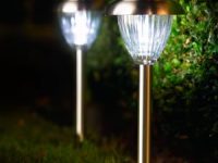
In some of our projects, we may want to measure the distance of an object from a point. Ultrasonic Distance Sensors are the best sensor which provides stable, accurate, precise, non-contact distance measurements from 2cm to 4m. Ultrasonic Sensors can be used to measure distance between moving or stationary objects. Being very accurate and stable, these devices find large number of applications in robotics fields. For example it can be used as an excellent replacement for IR sensors in a Micromouse. In this tutorial we will lean to interface an Ultrasonic Distance Sensor with PIC Microcontroller.
Here for demonstration we are using Rhydolabz Ultrasonic Distance Sensor with ASCII Output. It can be easily interfaced with a PIC Microcontroller using USART by just connecting the output pin of the sensor to RX pin of the microcontroller. In every 500ms this sensor transmits an ultrasonic burst and listens for its echo. The sensor sends out ASCII value corresponds to the time required for the ultrasonic burst to return to the sensor. The UART of the sensor is operates at a baud rate 9600 and the sensor can be powered by a 5V DC Supply. The ASCII output of the sensor will be equal to the distance to the obstacle in centimeter (cm).
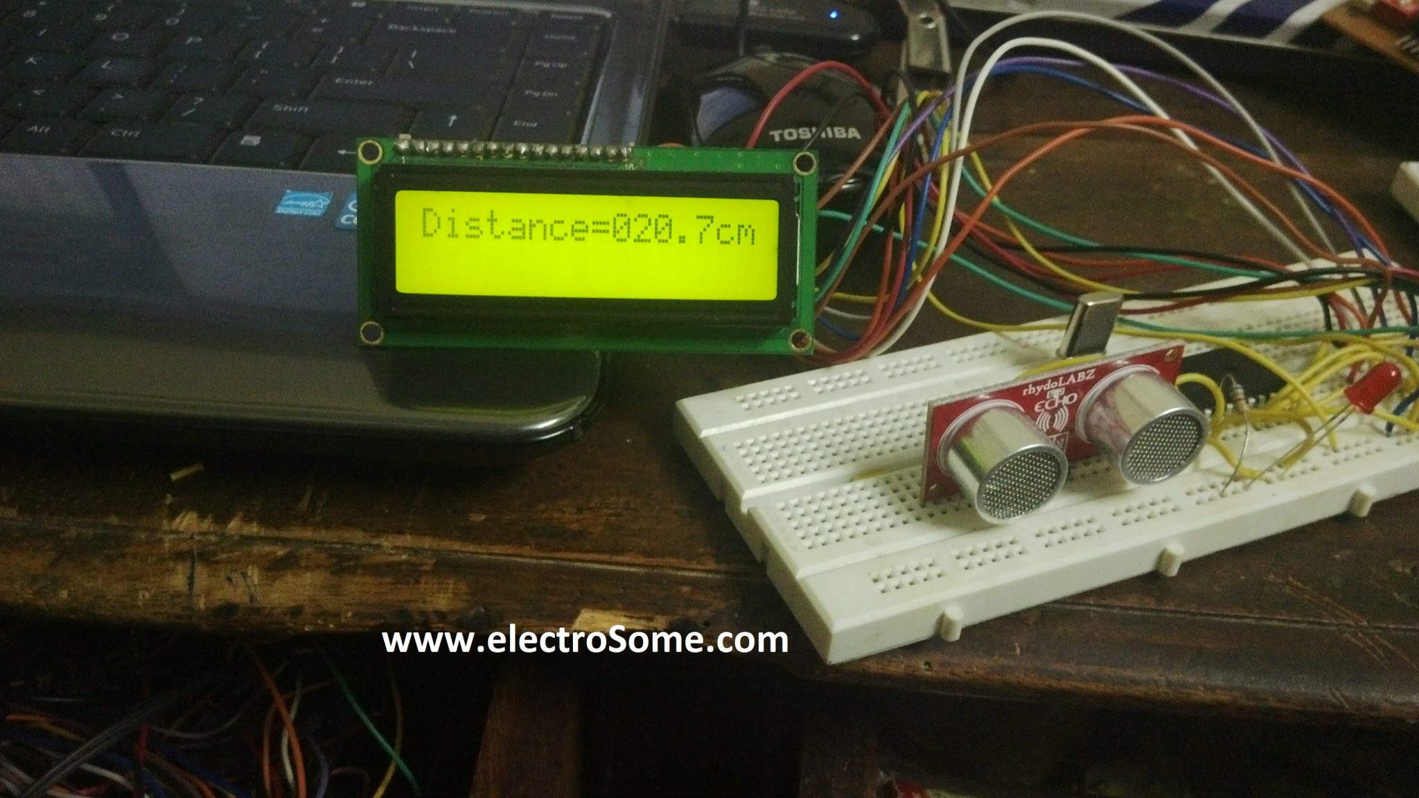
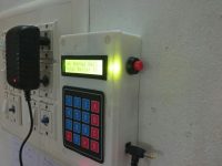
Ultrasonic Distance Sensor interfaced with PIC Microcontroller
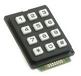
The sensor has three pins…
- Vcc – +5V DC Supply to the Sensor
- GND – Ground Level of the Power Supply
- SIG – Signal, Serial Data Out
Circuit Diagram
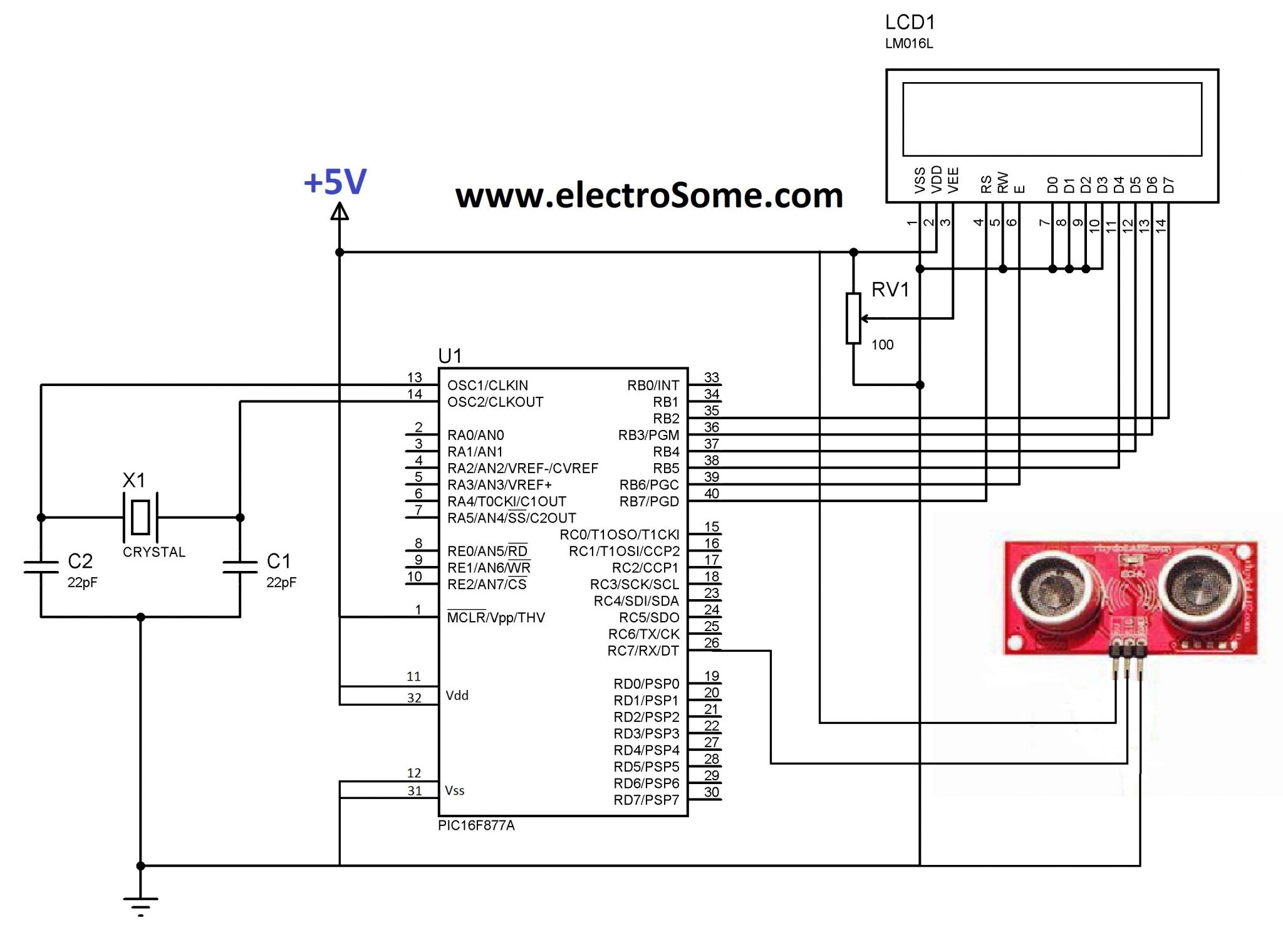
The sensor outputs distance in centimeter (cm) via USART. The output format can be found from the datasheet of the sensor as follows.
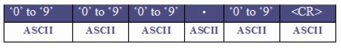
ASCII values corresponds to each character can be found from the following table.

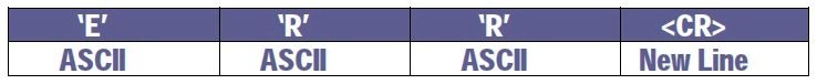
The sensor outputs error message if the target object distance is above 4.3m.
MikroC Program
// LCD module connections
sbit LCD_RS at RB7_bit;
sbit LCD_EN at RB6_bit;
sbit LCD_D4 at RB5_bit;
sbit LCD_D5 at RB4_bit;
sbit LCD_D6 at RB3_bit;
sbit LCD_D7 at RB2_bit;
sbit LCD_RS_Direction at TRISB7_bit;
sbit LCD_EN_Direction at TRISB6_bit;
sbit LCD_D4_Direction at TRISB5_bit;
sbit LCD_D5_Direction at TRISB4_bit;
sbit LCD_D6_Direction at TRISB3_bit;
sbit LCD_D7_Direction at TRISB2_bit;
// End LCD module connections

void main()
{
 int i;
 char dist[] = "000.0";
 Lcd_Init(); // Initialize LCD
 UART1_Init(9600); //Initialize the UART module
 Lcd_Cmd(_LCD_CLEAR); // Clear display
 Lcd_Cmd(_LCD_CURSOR_OFF); // Cursor off
 Lcd_Out(1,1,"Distance= cm");
 do
 {
   if(UART1_Data_Ready()) //if data ready
   {
     if(UART1_Read() == 0x0D) //check for new line character
     {
       for(i=0;i<5;)
       {
         if(UART1_Data_Ready()) // if data ready
         {
           dist[i] = UART1_Read();  // read data
           i++;
         }
       }
     }
   }
  Lcd_Out(1,10,dist);
}while(1);
}
I think the program is self explanatory. Every time program checks for new line character <CR> (0x0D), when it founds it, the program reads next 5 characters as the distance data. The distance data is assigned to a character array and is displayed in the LCD.
Buy Here
[products ids=”8605, 8838, 9566″]


My teacher has given me the task to do the same project which show output on dial like meter not on LCD or dial like mater in matlab to do this what should i do? need help
hello do you have the code for ultrasonic sensor with pic18f4550 for mplab xc8??
i tried it but i cant seem to get the distance displayed in cm on the LCD
https://electrosome.com/dc-motor-l293d-pic-microcontroller/
diffuse reflective mode ultrasonic sensor….
how to interface a motor to microcontroller and how to interface the signals sent by the sensor to motor on object detection
It depends on the type of ultrasonic sensor you are using. Which is the sensor you are using ?
Hello, i have followed the instructions exactly as they are described here but after downloading the hex to my pic through a velleman k8076 my microcontroller does not do anything… i’m reading back the hex from the microcontroller and it is loaded correctly but stil it does not do anything.. i have connected the display and the below line is just black. Any suggestion?
https://electrosome.com/hc-sr04-ultrasonic-sensor-pic/
can i use Ultrasonic sensors – HC-SR04 in this circuit in place of given sensor(Rhydolabz’s “ECHO” Ultrasonic Distance Sensor)?
Hello can I fined sensor hight power with frequency 59000 Penetrates ground to do gold detector
If you want cheap solution, use SR-04 ultrasonic sensor….. just test it with water..
Hi
I’m doing water level controller project of residential water tank. i decided to measure the level of water using ultrasonic sensor with cheap rate. please suggest what type of ultra sonic sensor should i use ? Will ultra sonic sensor detect the water level ?
please give details of the sensor and where to buy it ?
It should work up to.. 4m..
Are you using Rhydolabz sensor ?
I can able measured upto 40 cm only. can u pls give the procedure to measure upto 4meter?
Refer the datasheet of microcontroller..
Read its timer section.
I will write an article about it soon..
and one more thing how we read the timer value after stop nd by time of echo pulse how we calculate te distance????
kya ap mujay bna k day sktayy hai??? actually i m the beginner … nd its rquest to u… pllllzzzzz create this code???
This tutorial uses ASCII output sensor… the 4 pin sensor that you mentioned is a different one..
Hello,
It is my logic…
Sorry, Not Available
This is not simulated… but verified in hardware..
Nop,
It is very simple, follow these steps..
1. Trigger the module
2. Listen for echo
3. Start Timer when Echo comes
4. Stop Timer when Echo stops
5. Read the timer
6. Convert to distance
anybody have mplab code for just ultrasonic sensor???? nd how to connect the more numbers of sensors if numbers are other than one????nd plllzz tell me which ping ultrasonic sensor sensor is used here?????
It this you should use .. SR-05 ultrasonic sensor. .It is low cost.. and can be connected to any pin of pic microcontroller..
If you want to use above ascii output sensor.. you can use software uart libraries in mikroc pro
yes sandeep i also want to know how we use 2 or 3 sensors simultaneously….
if u got ur answer then plz tell me……
how can we use 2 of the sensors at a time .it is working individually bbut some problem when using 2 of them simultaneously
how it will calculates the distance and sends ascii output ?
can you please explain the internal operation of this serial ascii output sensor? internal block daigram?
i have 4 pin sensor, one trigger, 1 echo and 2 power pins, , can you please tell me the pin connection
why are we checking this input data ready ” UART1_Data_Ready()” twice?
please help me
with which software you simulated this project?
ultrasonic library don’t exist in proteus libraries.
plss send code for 8051 if u hav.
i need the isis diagram for this code
can this sensor works underwater ?
I haven’t yet used that sensor.. try reading its datasheet..
sir, is GH-311 ultrasonic sensor an ASCII output?
I used 8MHz crystal..
What is the crystal here??
5us PULSE??
This is ASCII output sensor.. it communicates using UART .. so no need of pulses..
sir what does this mean where is the 5us pulse for the sensor?
for(i=0;i<5;)
{
if(UART1_Data_Ready()) // if data ready
{
dist[i] = UART1_Read(); // read data
i++;
}
this code is written and tested only for the ultrasonic sensor prescribed in the article..
hello i used that idea and make every things same but i think the code not complete
because it dose not work with me . can a have full explanation about code ?
Yes… UART of most of the commonly used modules accept TTL logic… No need to use max232 here….
Now RS232 is rarely used…… it was used in older PC’s…. todays PC’s hasn’t any built in RS232….
So most of us use.. .USB to UART converter…. output of this converter is TTL compatible… not RS232..
Does USART of pic accept TTL logic? Do we need a max232 module to convert ultrasonic output signals to RS232 logic?
Use 2.2K ohm..
what’s RV1 stand for? is it resistance 100 ohm?
There is no ultrasonic components in proteus….
So to simulate it, you need to create the component… I haven’t yet created my own components in proteus…..
The above program can be built with mikroc pro compiler… to get the corresponding hex file..
plz i want to know how u simulate this circuit
if u use protes can u show me the HEX file
There is no library for ultrasonic distance sensor in proteus… so you can’t simulate…
HI, how can i simulate it at protues ISIS????
i understand yr circuit diagram but why the ultrasonic sensor display by a image???
yes.. it will send ASCII of 123.4 separately.. as given in the table..
how does the sensor send the data..i mean in what format..say the distance is 123.4 cm , then ll it send the ASCII of 123.4 separately .?? like ASCII of 4 , then ‘.’ , then ASCII of 3 etc..??
Sure, you proceed…
Please send us the code after completing the mplab code..
can i coding in MPlab… i new in progrm..
For simulating this in proteus.. you should create a new component (ultrasonic distance sensor) in proteus.. as it is not present in proteus library..
how to use this coding in proteus…. i use same circuit.. above
Not sure…. Just read its datasheet or manual….
I think.. when you provide trigger signal it sends an ultrasonic burst and gives echo signal when the ultrasonic burst receives back….. So to calculate distance you should use the equation Distance = time * velocity… where velocity is a constant..
I already have ultrasonic sensor with echo and trigger pins instead of SIG pin..Can i know how micropic program should be changed according to echo and trigger pins..
Please try it yourself.. arduino has all the required built in libraries… so just replace the functions used in this program.. to arduino functions.. it will work..
Can you please give me arduino code for the above ASCII output sensor? Can’t find it anywhere
Sorry I am little busy in these days.. Surely I wlll do it one day..
Please sir, do you have ccs c code for this?
Nope…
Do you have MPLAB program for this???
Sorry, it was used in other applications.. they are not needed here…So I removed them… thanks for the query..
1. char o[7]
Whats o here?
2. Why is ‘j’ initialised? Its nowhere used.
char o[7]
Whats o here?
Why is ‘j’ initialised? Its nowhere used.
for(i=0;i<5;)
Why isn't there an increment like i++?
RB is used instead of PORT register and TRIS itself a register. TRIS register is used to set the direction of each pins of that port while PORT register is used to set the status of each pin of that port…. Compiler needs these registers during Building process, since LCD can be connected to any of the pins of the microcontroller..
Why are these LCD pins initialised twice? Once as RB and next as TRISB? What is RB and TRISB(tri state buffer?) used for?
That question is answered..
These statements are used to tell the compiler that a 16X2 LCD is connected to the above defined pins… and the LCD display is accessed using Lcd_ etc functions…. Please go to this link to do this in 8051 using keil c
http://www.electrosome.com/interfacing-lcd-with-8051-using-keil-c-at89c51/
UART serial communication is used, you can use the internal USART module of 8051 for that..
Yes it is working fine… Its cost ranges from 15$ to 20$..
Sorry, Kindly convert the above code to 8051 by writing a UART function for it…
The module works fine right? Is it worth the buy?
Ligo George, even i have he query as MOHITH. can u please help me out or rather help us out?
Can you please explain me these?
sbit LCD_RS at RB7_bit;
sbit LCD_EN at RB6_bit;
sbit LCD_D4 at RB5_bit;
sbit LCD_D5 at RB4_bit;
sbit LCD_D6 at RB3_bit;
sbit LCD_D7 at RB2_bit;
sbit LCD_RS_Direction at TRISB7_bit;
sbit LCD_EN_Direction at TRISB6_bit;
sbit LCD_D4_Direction at TRISB5_bit;
sbit LCD_D5_Direction at TRISB4_bit;
sbit LCD_D6_Direction at TRISB3_bit;
sbit LCD_D7_Direction at TRISB2_bit;
I have no idea of your coding this platform, all I know is 8051. could you please explain me these LCD initializations in 8051 C programming words? What is the logic behind the serial communication? As in, how long should the SIG send out pulses and what should the delay be?
Do you have the 8051 code for this? If yes,please give me the link or the code itself.
It’s cost is about 20$. Yes.. it sends out ASCII values… PWM output sensors are also available in the market..
Whats the cost of this module? It sends out ASCII values?
thanks,,,
Nop, it depends on the ultrasonic sensor you use..
If it is ascii output ultrasonic sensor, it may work…
can i use some another ultrasonic sensor with this same code?? thanks..
Nop, I have used built in library functions of mikroC pro..
Did you use any header files? and if so which ones
Thanks
Thanx bro
Yes……
is it complete code?
Thanks this helped me a lot…thanks for sharing
I haven’t yet used hi-tech c compiler… try converting this code to hi-tech c..
If anybody give a c code for interface this distance sensor with pic16f877a for hi-tech c compiler….