

Digital Door Lock using Arduino
Contents
As thefts are increasing day by day security is becoming a major concern nowadays. In this project we will make a digital door lock system with keypad using Arduino Uno. It will open your door only when the right password is entered and it will start beeping when a wrong password is entered.
Components Required
- 4×4 keypad
- LCD
- Arduino Uno
- Push Pull Solenoid
- TIP 120 NPN transistor
- Power Supply
- Breadboard
- 1KΩ, 220Ω Resistor
- 10KΩ Potentiometer
- Buzzer
- Connecting wires
Circuit Diagram & Explanation
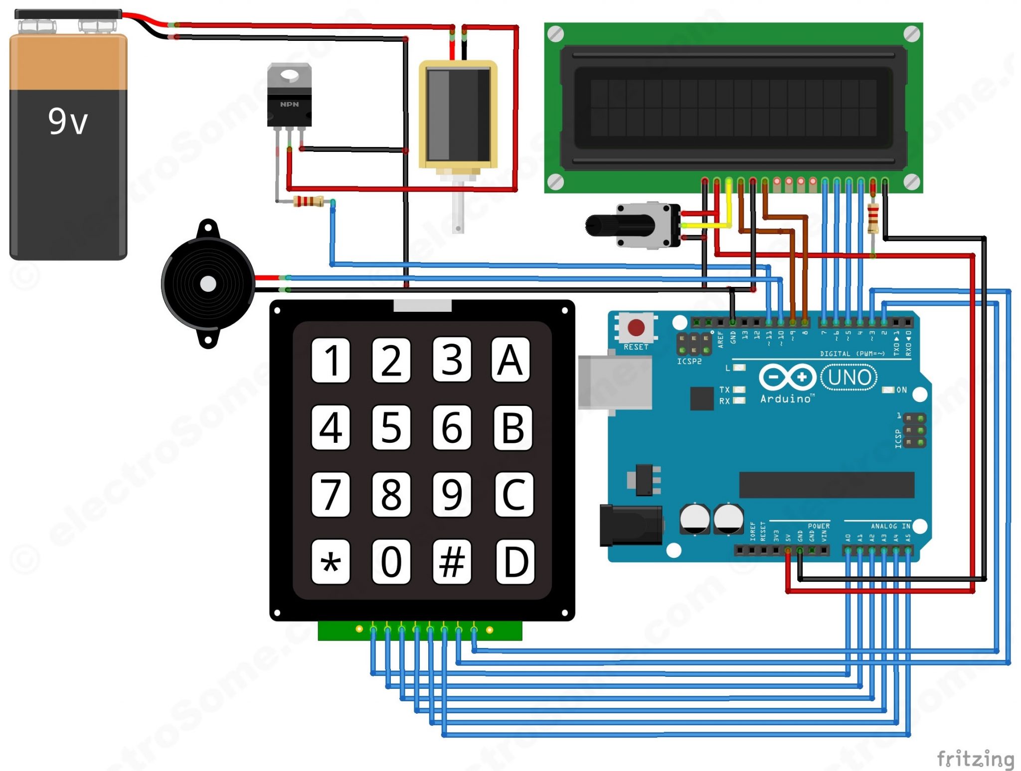
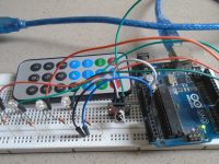
First of all, we will make the connection to the 4×4 Keypad. For connecting the keypad with the Arduino we are using both analog and digital pins. We used analog pins since we need more that 14 digitals pins for this project. If you are using Arduino Mega, then there is no need to use analog pins. Connect first six pins of keypad to analog pins A0 ~ A5 of Arduino and remaining two to digital pins 3 and 2.
To connect the push pull solenoid with the Arduino, we will have to use external power because it requires 6 ~ 12V to operate and much more current than the Arduino can provide. So to do that, we will use TIP120 NPN transistor as a switch/driver and a DC power source which can provide 6 ~ 12V. The NPN transistor will switch ON when we will give HIGH to its base. So, connect its first pin (which is the base pin) to the pin 11 through to a 1KΩ resistor, second pin (which is the collector pin) to the negative wire of push pull solenoid and third pin (which is the emitter pin) to the ground. Now connect the positive of power supply to the positive wire of solenoid and the negative of power supply to the ground.
Now connect the positive wire of buzzer to the pin 10 of Arduino and negative wire to the ground.
Now we will connect the 16×2 LCD to the Arduino.
- Connect pin 1 (VEE) to the ground.
- Connect pin 2 (VDD or VCC) to the 5V of the Arduino.
- Connect pin 3 (V0) to the middle pin of the 10KΩ potentiometer and connect the other two ends of the potentiometer to VCC and GND. The potentiometer is used to control the contrast of the LCD.
- Connect pin 4 (RS) to the pin 9 of the Arduino. This is Register Select pin used to select a particular register in the LCD driver, which is handled by the LCD library.
- Connect pin 5 (Read/Write) to the ground of Arduino. This pin is not often used so we will connect it to the ground as we are only writing data to LCD.
- Connect pin 6 (E) to the pin 8 of the Arduino. It is used indicate a valid data or command in the following data pins.
- The following four pins are data pins which are used to send data or commands to the LCD.
- Connect pin 11 (D4) to pin 7 of Arduino.
- Connect pin 12 (D5) to pin 6 of Arduino.
- Connect pin 13 (D6) to pin 5 of Arduino.
- Connect pin 14 (D7) to pin 4 of Arduino.
- Connect pin 15 to the VCC through the 220 ohm resistor. By changing this resitor value we can change the backlight LED brightness. Larger values will make the back light much more darker.
- Connect pin 16 to the Ground.
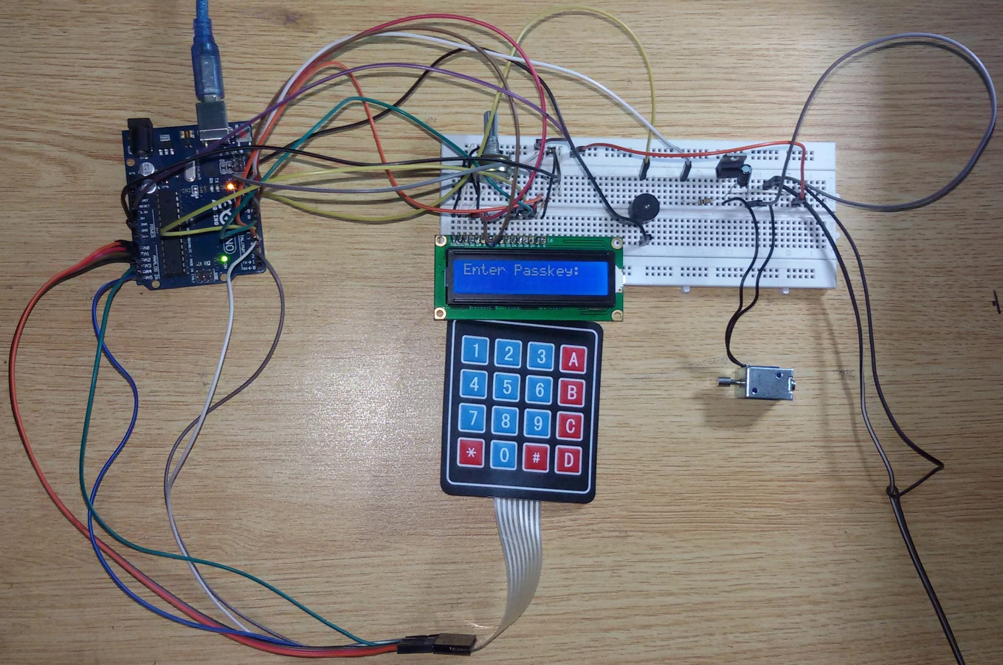
Working
In this project, we have used EEPROM in the Arduino to store the password in it. The default password stored in it will be ‘1234’. When we enter a password, it will match it with the password stored in the Arduino EEPROM. If it is correct, then it will show ‘Passkey Accepted’ and the push pull solenoid will come in low state (Door Unlocked). If the password is wrong, then it will show ‘Access Denied’. During this condition the buzzer will start beeping and the push pull solenoid will remain in the high state (Door Locked). The buzzer will also beep once when any key is pressed.
For changing the passkey, we have to press ‘#’. When we press ‘#’, it will ask for current passkey. If we enter the correct password it will ask for new passkey and will save it in the EEPROM.
Arduino Code or Sketch
#include <Keypad.h>
#include<LiquidCrystal.h>
#include<EEPROM.h>
LiquidCrystal lcd(9,8,7,6,5,4);
char password[4];
char pass[4],pass1[4];
int i=0;
char customKey=0;
const byte ROWS = 4; //four rows
const byte COLS = 4; //four columns
char hexaKeys[ROWS][COLS] = {
{'1','2','3','A'},
{'4','5','6','B'},
{'7','8','9','C'},
{'*','0','#','D'}
};
byte rowPins[ROWS] = {A0,A1,A2,A3}; //connect to the row pinouts of the keypad
byte colPins[COLS] = {A4,A5,3,2};   //connect to the column pinouts of the keypad
//initialize an instance of class NewKeypad
Keypad customKeypad = Keypad( makeKeymap(hexaKeys), rowPins, colPins, ROWS, COLS);
int led;
int buzzer = 10;
int m11;
int m12;
void setup()
{
  Serial.begin(9600);
  pinMode(11, OUTPUT);

  lcd.begin(16,2);
  pinMode(led, OUTPUT);
  pinMode(buzzer, OUTPUT);
  pinMode(m11, OUTPUT);
  pinMode(m12, OUTPUT);
  lcd.print(" Electronic ");
  Serial.print(" Electronic ");
  lcd.setCursor(0,1);
  lcd.print(" Keypad Lock ");
  Serial.print(" Keypad Lock ");
  delay(2000);
  lcd.clear();
  lcd.print("Enter Ur Passkey:");
  Serial.println("Enter Ur Passkey:");
  lcd.setCursor(0,1);
  for(int j=0;j<4;j++)
    EEPROM.write(j, j+49);
  for(int j=0;j<4;j++)
    pass[j]=EEPROM.read(j);
}

void loop()
{
  digitalWrite(11, HIGH);
  customKey = customKeypad.getKey();
  if(customKey=='#')
    change();
  if (customKey)
  {
    password[i++]=customKey;
    lcd.print(customKey);
    Serial.print(customKey);
    beep();
  }
  if(i==4)
  {
    delay(200);
    for(int j=0;j<4;j++)
      pass[j]=EEPROM.read(j);
    if(!(strncmp(password, pass,4)))
    {
      digitalWrite(led, HIGH);
      beep();
      lcd.clear();
      lcd.print("Passkey Accepted");
      Serial.println("Passkey Accepted");
      digitalWrite(11, LOW);
      delay(2000);
      lcd.setCursor(0,1);
      lcd.print("#.Change Passkey");
      Serial.println("#.Change Passkey");
      delay(2000);
      lcd.clear();
      lcd.print("Enter Passkey:");
      Serial.println("Enter Passkey:");
      lcd.setCursor(0,1);
      i=0;
      digitalWrite(led, LOW);
    }
    else
    {
      digitalWrite(11, HIGH);
      digitalWrite(buzzer, HIGH);
      lcd.clear();
      lcd.print("Access Denied...");
      Serial.println("Access Denied...");
      lcd.setCursor(0,1);
      lcd.print("#.Change Passkey");
      Serial.println("#.Change Passkey");
      delay(2000);
      lcd.clear();
      lcd.print("Enter Passkey:");
      Serial.println("Enter Passkey:");
      lcd.setCursor(0,1);
      i=0;
      digitalWrite(buzzer, LOW);
    }
  }
}
void change()
{
  int j=0;
  lcd.clear();
  lcd.print("UR Current Passk");
  Serial.println("UR Current Passk");
  lcd.setCursor(0,1);
  while(j<4)
  {
    char key=customKeypad.getKey();
    if(key)
    {
      pass1[j++]=key;
      lcd.print(key);
      Serial.print(key);
      beep();
    }
    key=0;
  }
  delay(500);

  if((strncmp(pass1, pass, 4)))
  {
    lcd.clear();
    lcd.print("Wrong Passkey...");
    Serial.println("Wrong Passkey...");
    lcd.setCursor(0,1);
    lcd.print("Better Luck Again");
    Serial.println("Better Luck Again");
    delay(1000);
  }
  else
  {
    j=0;
    lcd.clear();
    lcd.print("Enter New Passk:");
    Serial.println("Enter New Passk:");
    lcd.setCursor(0,1);
    while(j<4)
    {
      char key=customKeypad.getKey();
      if(key)
      {
        pass[j]=key;
        lcd.print(key);
        Serial.print(key);
        EEPROM.write(j,key);
        j++;
        beep();
      }
    }
    lcd.print(" Done......");
    Serial.println(" Done......");
    delay(1000);
  }
  lcd.clear();
  lcd.print("Enter Ur Passk:");
  Serial.println("Enter Ur Passk:");
  lcd.setCursor(0,1);
  customKey=0;
}
void beep()
{
  digitalWrite(buzzer, HIGH);
  delay(20);
  digitalWrite(buzzer, LOW);
}
Explanation
First of all, we will include libraries for the Keypad, LCD and EEPROM. The default password saved in the EEPROM will be ‘1234’. Then initializing the library for LCD and defining pins on which the LCD is connected.
#include <Keypad.h>
#include<LiquidCrystal.h>
#include<EEPROM.h>
LiquidCrystal lcd(9,8,7,6,5,4);
Then defining pins for connecting 4×4 keypad. We are using 4×4 keypad therefore we will define 4 pins for rows and 4 pins for columns. If you are using 4×3 keypad then you need only 4 pins for rows and 3 pins for columns.
const byte ROWS = 4; //four rows
const byte COLS = 4; //four columns
char hexaKeys[ROWS][COLS] = {
{'1','2','3','A'},
{'4','5','6','B'},
{'7','8','9','C'},
{'*','0','#','D'}
};
byte rowPins[ROWS] = {A0,A1,A2,A3}; //connect to the row pinouts of the keypad
byte colPins[COLS] = {A4,A5,3,2};   //connect to the column pinouts of the keypad
Then giving command to start the LCD, setting buzzer and make LED pins as output.
  lcd.begin(16,2);
  pinMode(led, OUTPUT);
  pinMode(buzzer, OUTPUT);
  pinMode(m11, OUTPUT);
  pinMode(m12, OUTPUT);
  lcd.print(" Electronic ");
  Serial.print(" Electronic ");
  lcd.setCursor(0,1);
  lcd.print(" Keypad Lock ");
  Serial.print(" Keypad Lock ");
  delay(2000);
The following code will read pressed keys from the keypad and will show it on LCD as well as in serial monitor. Arduino will read keys one by one and make a beep sound whenever a key is pressed.
  digitalWrite(11, HIGH);
  customKey = customKeypad.getKey();
  if(customKey=='#')
    change();
  if (customKey)
  {
    password[i++]=customKey;
    lcd.print(customKey);
    Serial.print(customKey);
    beep();
  }
The following code will compare the entered key with the password stored in the EEPROM. If the password is correct, then it will show ‘Passkey Accepted’ otherwise it will show ‘Access Denied’.
  if(i==4)
  {
    delay(200);
    for(int j=0;j<4;j++)
      pass[j]=EEPROM.read(j);
    if(!(strncmp(password, pass,4)))
    {
      digitalWrite(led, HIGH);
      beep();
      lcd.clear();
      lcd.print("Passkey Accepted");
      Serial.println("Passkey Accepted");
      digitalWrite(11, LOW);
      delay(2000);
      lcd.setCursor(0,1);
      lcd.print("#.Change Passkey");
      Serial.println("#.Change Passkey");
      delay(2000);
      lcd.clear();
      lcd.print("Enter Passkey:");
      Serial.println("Enter Passkey:");
      lcd.setCursor(0,1);
      i=0;
      digitalWrite(led, LOW);
    }
The following code will change the password stored in the EEPROM. When we press the ‘#’ key to change the password. Then it will ask you to enter the current password and if it is correct then it will ask you to enter the new password. Then it will store this new password in the EEPROM.
  int j=0;
  lcd.clear();
  lcd.print("UR Current Passk");
  Serial.println("UR Current Passk");
  lcd.setCursor(0,1);
  while(j<4)
  {
    char key=customKeypad.getKey();
    if(key)
    {
      pass1[j++]=key;
      lcd.print(key);
      Serial.print(key);
      beep();
    }
    key=0;
  }
  delay(500);

hi….
am grateful for sharing this wonderful project, i did same but i replaced the motor with a servo, using VarSpeedservo library which worked perfectly well as the door access, but i wanted adding a switch that if when pressed, the system will work as if you entered the right pin so to allow one come out of the entrance easily.. is really giving me issue.. thanks
Hi, how i change password in EEPROM?
is there a way of allowing the user to input their own time with the same keypad, say pressing a takes you to a timer like interface that allows for the user to input their time in munites and the arduino multiplies this by 60 and keeps the solenoid on high for that time, and when its over it retracts the solenoid????
Can I use L293D motor driver instead of using TIP120?
Because I am using normal DC motor not solenoid motor
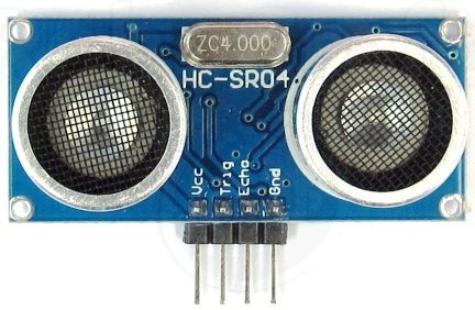
“I am ready maked,with hc-sr04.But after compile ( no error with ide 1.6.8) and trying,there is no signal/pulse.
Everything is working fine but Solenoid is staying on high state only even after entering correct password. I used 12V solenoid and 12 V battery. What should I do?
please send the full coding for this circuit https://uploads.disquscdn.com/images/256c5615131aa8de4643ca9edc8d013237ac251494654d5554a780cf99ca0dbd.jpg
can you send the full cording of this circuit from the beginning
the cording u entered is not work
If you need long lasting battery life, you can use sleep feature which will consume very less power when it is not in use.
Will the battery long last? If yes, what is battery’s working period?
Can I get the schematic in multisim please ?
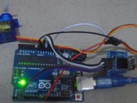
How can I use a servo instead of DC motor
https://uploads.disquscdn.com/images/a450c660dcfb9121e950757905afc380a006bdcdb7d6dfa16dae87e0f2577e4d.jpg
i have a problem with LCD display. i checked the circuit twice.code is running OK.but no display on LCD.
i use black wire on right side AS a (1) on Lcd ,,, is this right or not ..see in the picture
Is it possible to add ultrasonic sensor in this circuit so that I can use it as water level controller to select required water level help with code please
hey, I have similar project, but the different is that I will use a Steeper Motor as an output instead of Push Pull Solenoid. The problem that I faced was the code, how can I use stepper motor in my code (MY IDEA IS EXACTLY SIMILAR TO YOUR PROJECT BUT I WOULD USE STEPPER MOTOR), so could you help me over that please.